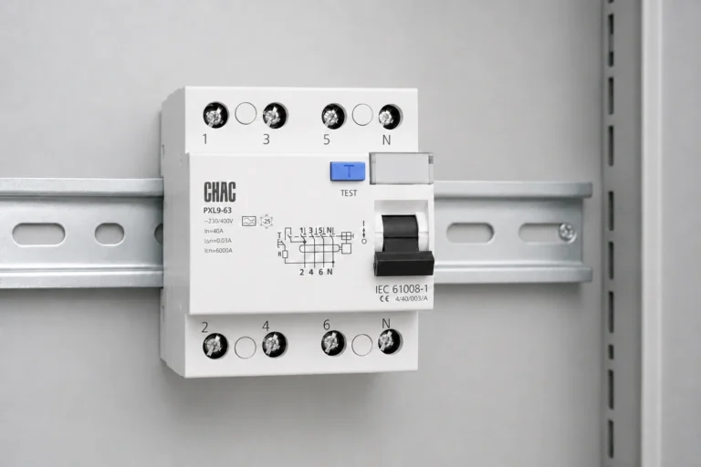
Ac contactor wiring diagram selection starts with the circuit role, the project requirement, and selected-model documentation. AC Contactor Control Wiring: Interface Checks for Panel Builders helps panel builders organize those checks before a device is specified or an RFQ is issued. Control-wiring acceptance stays with the qualified panel designer and the contactor instructions that match the purchased model.
Índice
- Part 1. What should an AC contactor wiring diagram show first?
- Part 2. Which interface checks belong before a wire is landed?
- Part 3. How should the main and control circuits stay distinct?
- Part 4. Where do auxiliary contacts need a documented role?
- Part 5. What should a panel-builder RFQ include?
- Part 6. Which CHAC page is appropriate for a product discussion?
- Part 7. Where does contactor wiring guidance end for panel builders?
Part 1. What should an AC contactor wiring diagram show first?
Read the control circuit separately from the main power circuit. The control drawing should identify the coil command path, the intended supply and control interface, the stop or permissive logic, auxiliary feedback, and the terminal references used by the selected contactor documentation.
Part 2. Which interface checks belong before a wire is landed?
Confirm the selected coil data, control supply, terminal identification, drawing revision, protective devices, interlocks, and feedback requirement. These are interface checks, not a universal wiring prescription, because terminal arrangements and accessory behavior vary by the selected model.
Part 3. How should the main and control circuits stay distinct?
The power path carries the controlled load through the main contacts, while the control path commands the coil and processes permissive or feedback signals. Keeping the two paths visually distinct on the drawing helps the panel team avoid treating a control contact as a power-terminal substitute.
Important: A generic contactor wiring sketch cannot authorize landing wires on a live or unfinished panel; selected-model terminals and lockout procedures remain controlling. (fuente — Eaton control-panel design guide and IEC contactor references)
Part 4. Where do auxiliary contacts need a documented role?
Auxiliary contacts may be used for indication, electrical interlocking, seal-in logic, or feedback, but their intended normal state and function must be shown on the control drawing. Confirm the exact accessory and contact arrangement from the selected product documentation before relying on it in logic.
Part 5. What should a panel-builder RFQ include?
Include the control schematic, load and circuit role, selected coil requirement, desired auxiliary functions, enclosure and terminal constraints, requested drawings, target project requirements, and any branding or packaging need. A supplier can then respond against defined interfaces instead of guessing from a generic wiring diagram.
Una lista de entradas de RFQ compacta facilita la comparación de las respuestas de los proveedores:
| El comprador debe proporcionar | Por qué importa | Error común |
|---|---|---|
| Conjunto de planos actual | Define el límite del circuito | Envío del nombre de un producto sin un diagrama |
| Funciones requeridas | Hace que la solicitud sea revisable | Tratar opciones no verificadas como estándar |
| Contexto de instalación | Identifica las condiciones del proyecto para confirmar | Asumiendo que la copia de la categoría es una aprobación del proyecto |
| Solicitud de documentación | Conecta la RFQ con la evidencia exacta | Aceptando afirmaciones genéricas en lugar de datos del modelo |
| Enviar con cotización | Hace que la comparación de proveedores sea verificable | Citando sin el paquete de evidencia solicitado |
Para un contexto más amplio, revise el ac contactor wiring diagram product family y lo relacionado página de línea de productos.
Part 6. Which CHAC page is appropriate for a product discussion?
Use the CQC6 industrial AC contactor page for a product-family discussion after the control interfaces are defined, and use the AC contactor category for broader context. This is a sourcing step, not an assertion that one contactor or accessory matches every control diagram.
Recomendación de producto
Fabricante OEM de contactores de CA industriales serie CQC6 | CHAC Electric
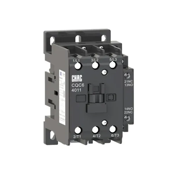
Utilice el publicado página de producto CHAC relevante as a documented product route starting point for a product discussion only after the RFQ inputs are complete. Branded industrial-control packaging requests can go through the industrial-control customization page. A look-alike contactor body does not prove coil data, auxiliary arrangement, or terminal marking for the control schematic.
Part 7. Where does contactor wiring guidance end for panel builders?
This article supports drawing review and RFQ preparation for panel builders. It is not live electrical work guidance, a substitute for lockout procedures, or authority to wire a specific unit without the selected product instructions and qualified project review. Require a drawing review of coil supply, permissives, and auxiliary feedback before wires are planned on the door.
Fit Boundary: contactor interface checks support drawing review only; they are not live wiring instructions or lockout procedures.
Lectura relacionada: un artículo de CHAC más específico y ya publicado está enlazado por contexto, no como un sustituto del alcance de decisión de este artículo.
Share the control schematic and coil interface notes through Contactar a CHAC Electric when you need a contactor product-route review.
Preguntas frecuentes
What is the first check on an AC contactor wiring diagram?
Separate the main power path from the control path, then identify the coil command and the selected product’s terminal references.
Can a generic wiring diagram replace the selected contactor instructions?
No. A generic diagram helps organize questions, but selected-model instructions govern terminals, coil data, accessory arrangement, and installation details.
Why are auxiliary contacts shown separately from main contacts?
They serve control, feedback, indication, or interlocking functions and should not be assumed to carry the same duty as the main power contacts.
What should be shown for a contactor coil interface?
Show the control source, coil terminal references, command and permissive devices, protective arrangement, and the conditions that energize or de-energize the coil.
What information should a contactor control-circuit RFQ contain?
Provide the control schematic, coil requirement, auxiliary functions, circuit role, assembly constraints, requested documents, and the relevant project conditions.
When should a qualified designer review the final control circuit?
Review it before manufacture, commissioning, or energization, after the selected contactor and all accessories have been confirmed from their documentation.