Un contacteur brûlé peut sembler expliquer l’arrêt d’un système CVC, mais son remplacement ne permet pas de déterminer la cause de sa défaillance. Une alimentation de commande instable, une borne endommagée, un régime de commutation inadapté ou une panne du compresseur peuvent solliciter le nouveau contacteur de la même manière. La question essentielle est de savoir si l’appareil reçoit une commande valide, se ferme correctement et fournit de l’énergie à une charge en état de fonctionner. Il s’agit là de vérifications distinctes, et les confondre peut entraîner des coûts répétés de pièces détachées et des temps d’arrêt prolongés. Ce guide explique le rôle du contacteur, la manière dont les techniciens qualifiés distinguent les défauts de commande des défauts de contacts et de charge, ainsi que les documents justificatifs nécessaires pour prendre une décision de remplacement.
La réponse courte est qu’un contacteur HVAC permet à un circuit de commande de faible puissance de commuter un compresseur, un ventilateur de condenseur, un chauffage ou un circuit de pompe. Un diagnostic fiable distingue la commande de la bobine de la réponse des contacts et de la charge. Un remplacement doit correspondre à la tension et à la fréquence vérifiées de la bobine, à la disposition des pôles, au classement de service de la charge, à la fréquence de commutation, aux bornes et à l’environnement. La norme IEC 60947-4-1 fournit un cadre standard pour les contacteurs et les démarreurs de moteur, mais ne constitue pas une preuve que tel ou tel remplacement convient à l’équipement. Demandez à un technicien qualifié d’enregistrer les exigences du circuit installé avant de choisir une pièce ; un ampérage identique ne suffit pas.
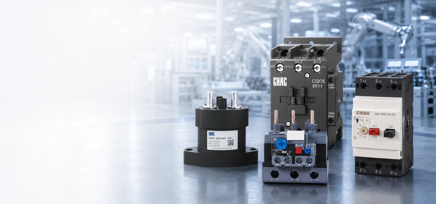
Un contacteur est un interrupteur à commande électrique conçu pour le contrôle à distance. Sa bobine est commandée par un thermostat, un automate de gestion technique du bâtiment ou un circuit de sécurité. Dans une conception électromagnétique classique, le mécanisme ferme alors les contacts principaux qui conduisent le courant plus élevé requis par la charge. Cette séparation permet d’éviter que le courant du compresseur n’atteigne les dispositifs de commande sensibles et rend possible la mise en séquence ainsi que l’interverrouillage.
L’idée de base est simple, mais des erreurs de remplacement surviennent parce que le circuit d’alimentation et le circuit de commande ont des exigences différentes. La tension alimentant le compresseur n’a pas nécessairement à être la même que celle alimentant son… Bobine de contacteur. Des cadres similaires peuvent également présenter des fréquences de bobine, des puissances nominales du moteur, des contacts auxiliaires ou des limites environnementales différentes.
À quoi sert un contacteur HVAC à l’intérieur du système ?
Comment la bobine transforme-t-elle un signal de commande en mouvement mécanique ?
Dans un conventionnel normalement ouvert Dans un contacteur, un ressort maintient l’armature mobile écartée du noyau magnétique à l’état de repos. Lorsque le circuit de commande applique la tension nominale, la bobine génère un flux magnétique. L’armature se déplace, la pression de contact augmente et les pôles principaux se ferment. Pour de nombreuses bobines CA conventionnelles, la puissance apparente requise au moment de l’attraction diffère de celle nécessaire une fois le circuit magnétique fermé ; les conceptions de bobines électroniques peuvent présenter un comportement différent.
Cette distinction explique pourquoi la fiche technique d’une bobine peut indiquer à la fois la puissance VA au démarrage et la puissance VA en régime permanent. Un transformateur de commande sélectionné uniquement sur la base de sa consommation en régime permanent risque de ne pas pouvoir assurer l’enclenchement simultané de plusieurs dispositifs. Les sorties de commande électroniques peuvent également être soumises à des limites de courant momentané. Vérifiez les caractéristiques précises de la bobine ainsi que la capacité de la source d’alimentation de commande, plutôt que de supposer que toutes les bobines de même tension imposent la même charge.
Pourquoi les contacts principaux et auxiliaires ne sont-ils pas interchangeables ?
Les contacts principaux commandent le compresseur, le ventilateur, la pompe ou le circuit de chauffage électrique. Les contacts auxiliaires transmettent des signaux de commande pour la notification d’état, l’interverrouillage électrique ou la séquence de fonctionnement. Leur état normal et leurs caractéristiques nominales doivent être conformes à la logique initiale ; un contact auxiliaire apparemment inutilisé peut s’avérer essentiel pour une séquence de sécurité ou de mise en marche progressive. La valeur nominale de courant d’un contact auxiliaire ne constitue en aucun cas une autorisation de l’utiliser à la place d’une pôle de charge principale. Un contacteur de compresseur doit être choisi en fonction du service moteur et du circuit de commande propres à l’équipement concerné. Les termes « contacteur de climatisation » et « contacteur magnétique pour climatisation » sont des désignations courantes de cet organe de commutation, mais ils ne constituent pas des spécifications complètes pour son remplacement.
Un contacteur n’est pas un dispositif de protection complet. La protection contre les surcharges réagit aux surintensités prolongées, tandis qu’un fusible ou un disjoncteur interrompt le courant de défaut. Ces fonctions peuvent être assurées séparément ou intégrées ailleurs dans l’équipement. Le guide à Contacteurs de surcharge et protection des moteurs explique pourquoi la commutation et la protection doivent être coordonnées plutôt que considérées comme interchangeables.
Comment les techniciens doivent-ils diagnostiquer un contacteur de CVC ?
Sûr Dépannage des contacteurs Il suit le signal tout au long du circuit, plutôt que de passer directement d’un symptôme à une pièce. Un technicien qualifié commence par confirmer la commande d’activation et l’état des dispositifs de sécurité. Les vérifications suivantes permettent de déterminer si la tension adéquate atteint la bobine dans les conditions réelles d’enclenchement, si l’armature prend correctement appui et si les contacts fermés fournissent la tension attendue à la charge.
Les compartiments électriques peuvent contenir des tensions dangereuses, une charge résiduelle et des équipements en mouvement automatique. Dans les lieux de travail couverts aux États-Unis, 1910.333 Sélection et utilisation des pratiques de travail Les pièces actives exposées doivent être mises hors tension, sauf si les exceptions spécifiées s’appliquent. Les travaux sur des pièces sous tension sont régis par des restrictions s’appliquant aux personnes qualifiées et par des mesures de protection appropriées. Les observations ci-dessous constituent une logique de diagnostic destinée au personnel formé et ne constituent pas une procédure de travail sous tension.
| Symptôme observé | Evidence to collect | Possible fault families | Why replacement alone may fail |
|---|---|---|---|
| No pull-in when cooling is requested | Control command, safety-chain state, coil marking, and voltage at the coil | Open safety, wiring fault, failed controller, open coil, or wrong coil | The contactor may never receive a valid command |
| Buzzing or rapid chatter | Voltage before and during pull-in, transformer output, connections, and armature seating | Undervoltage, excessive circuit drop, contamination, mechanical obstruction, or frequency mismatch | A new coil can chatter under the same unstable supply |
| Coil pulls in but the load does not start | Line voltage, voltage delivered through each closed pole, protection state, and load condition | Open or high-resistance contact, lost phase, protection operation, wiring fault, or failed load | The compressor or upstream circuit may be the root cause |
| Localized heating or discoloration | Terminal condition, conductor suitability, torque history, current balance, and contact voltage drop | Loose termination, overload, eroded contact, corrosion, or repeated chatter | Heat damage can extend into conductors and the enclosure |
| Load continues after the command ends | Coil command after shutdown, mechanical release, and isolated contact condition | Welded contacts, binding mechanism, back-fed control voltage, or logic fault | The control circuit must be ruled out before condemning the device |
Why can a normal coil-voltage reading miss a pull-in problem?
A plausible unloaded reading does not establish that the control supply can deliver the coil’s pull-in burden. A reading taken only after the armature has seated can also miss a brief voltage dip. For an authorized diagnostic test, the qualified technician records the voltage at the coil during the command, pull-in, and holding state, then compares those distinct conditions with the exact manufacturer’s operating limits. There is no universal voltage tolerance that can replace the model’s documentation.
If the voltage falls only during pull-in, the investigation shifts to the control transformer, simultaneous secondary loads, and the series devices or connections in the control path. Long conductors, poor connections, or a marginal controller output may contribute. If voltage remains within the specified limits but the armature fails to seat, mechanical condition and coil identity become more important. Neither result alone proves that the compressor is healthy.
What can contact voltage drop show that continuity cannot?
A deenergized continuity check can show that a contact closes, but it does not prove that it carries load without excessive resistance. During an authorized loaded test, the technician evaluates the voltage across each closed pole and any imbalance, using the manufacturer’s criteria where available. An abnormal result can involve contact erosion, contamination, insufficient pressure, or a damaged termination; it should be interpreted alongside load current rather than against an invented universal millivolt threshold.
The timing matters too. Coil behavior during armature movement and load-side behavior after seating are different observations. Combining them into a single statement such as “voltage is normal” can conceal a control-supply dip or a contact fault.
Can noise come from something other than damaged contacts?
Dust, insects, corrosion, or debris on magnetic faces can obstruct closure. Loose mounting and equipment vibration may amplify hum. An AC coil intended for a different frequency may not operate as specified. Inspection should therefore cover the enclosure, mechanism, mounting, coil marking, ambient conditions, and moisture evidence, not just the visible contact faces. Noise alone is not a conclusive failure test.
What Determines Contactor Life in HVAC Service?
Manufacturers distinguish mechanical life from electrical life. Mechanical-life figures describe operation without the electrical wear caused by switching the rated load. Electrical life depends on the current and voltage being switched, load type, switching duty, and operating frequency. A catalog’s largest life figure may therefore describe conditions unlike the installed HVAC duty. An air compressor contactor can also face a different start frequency and control sequence from a refrigeration compressor contactor. Compare the equipment instructions and actual switching duty before using one application as the sizing or service-life reference for the other.
Why does switching duty matter more than frame amperes?
The utilization-category framework in CEI 60947-4-1 distinguishes switching duties. AC-1 generally covers non-inductive or slightly inductive loads; AC-3 covers starting a squirrel-cage motor and switching it off while running; AC-4 covers more severe duties such as inching or plugging. A device’s AC-1 current cannot be assumed to equal its AC-3 motor rating.
For a compressor, identify the rating the equipment manufacturer actually requires. North American definite-purpose contactor documentation may specify full-load amperes, locked-rotor amperes, horsepower, or resistive-load ratings. An IEC motor rating at another voltage, or a higher resistive-current label, does not by itself establish compressor-duty suitability. Compare the exact product’s declared duty, voltage, phases, starting demands, and conditions of use with the equipment instructions.
What should be recorded when a replacement fails again?
Repeated starts, abnormal starting duration, voltage problems, and motor overload are separate stresses. Schneider Electric’s Fonctions de protection du moteur, last edited August 5, 2026, identifies rapid-cycle lockout, long-start protection, overload protection, and voltage-related protection as distinct functions. This general guidance does not prove that a particular HVAC unit includes them; its diagram and controller documentation must show what is actually implemented.
For repeat failures, retain the equipment and contactor identities, coil marking, failure time, command state, pull-in and holding observations, load-current findings, terminal condition, and relevant controller or protection events. Record whether the event follows a restart, a long idle period, simultaneous staging, or a protection operation. Comparing the failed and replacement devices with that event record is more useful than repeatedly increasing the contactor’s frame size. Compressor restart limits must come from its manufacturer, not a universal starts-per-hour rule.
Contact welding and severe pitting are outcomes, not complete diagnoses. Supply disturbances, load faults, poor terminations, chatter, and an incorrect duty rating can leave similar evidence. Correcting the original stress is part of the repair. Where the design requires separate overload protection, a relais de surcharge thermique must be selected and coordinated for the actual motor and starter; adding one is not a substitute for diagnosing a compressor fault.
When is a contact kit an acceptable repair?
Some industrial contactors have manufacturer-approved replacement coils or contact kits. Renewal can be reasonable when the exact design supports field service, the frame and arc-control parts remain undamaged, trained personnel follow the instructions, and post-service checks verify operation. The parts and device identity must remain traceable.
Complete replacement may be necessary when the housing, mechanism, coil, terminals, or arc-control parts are compromised, or when authorized renewal parts are unavailable. Filing or sanding contact faces should not be treated as an approved repair unless the manufacturer explicitly permits that procedure. A visually cleaner surface does not establish restored contact geometry or rated performance.
How Do You Specify a Compatible Replacement?
A reliable replacement starts with the equipment wiring diagram and full markings on the installed device. A photo helps identify layout but cannot verify coil burden, motor duty, or conditions of use. If markings are damaged or conflict with the diagram, consult current equipment documentation rather than guessing from appearance.
| Specification item | What to record | Risk if omitted |
|---|---|---|
| Charge admissible | Compressor, fan, heater or pump; motor data; starting method; applicable compressor, utilization or horsepower rating | A resistive-load ampere value may be misapplied to a motor |
| Main circuit | Voltage, phase, frequency, poles, operational current, and protection arrangement | Contacts may be underrated or the switching arrangement may differ from the equipment design |
| Control circuit | Coil voltage and frequency, inrush and holding characteristics, source capacity, suppression, and terminal layout | The device may fail to pull in or exceed the controller’s output capability |
| Switching pattern | Starting frequency, operating sequence, interlocks, and auxiliary-contact states | The selected duty may not cover the installed operation |
| Installation environment | Ambient limits, enclosure, moisture, contamination, vibration, altitude, conductors, and terminals | Electrical or mechanical conditions may exceed the published limits |
| Market documentation | Destination, product standard, listing or certification scope, drawings, labels, and permitted replacement arrangements | A physically compatible part may still be unacceptable for the equipment |
The contactor must also fit the protection and isolation strategy. A disconnect may provide the designated isolation function, while a contactor provides commanded switching; neither role should be inferred solely from appearance. Review the load requirements using the same discipline described in choosing the right motor contactor. The fuse or breaker, available fault current, and equipment short-circuit rating also need their own documented review.
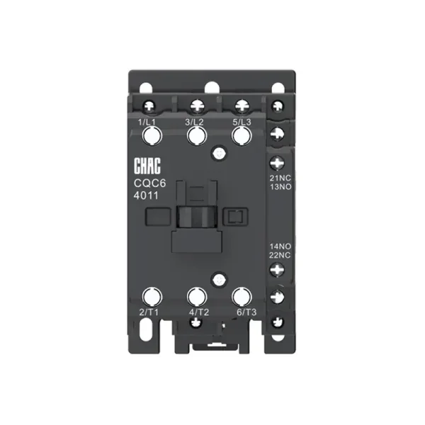
For an OEM or replacement program, approve a complete record rather than a shorthand cross-reference. A buyer evaluating an AC contactor replacement should confirm ratings for the intended voltage and duty, coil characteristics, accessories, mounting, terminal capacity, ambient limits, and required documentation. Track revisions across repeat orders so a coil or auxiliary-contact change is reviewed before it reaches the assembly line. A CHAC product-family page is a starting point for documentation, not evidence of interchangeability with an installed HVAC part.
Which Standards and Safety Rules Shape the Selection?
IEC 60947-4-1 covers electromechanical contactors and motor-starters within low-voltage switchgear and controlgear. It provides performance and verification requirements. A utilization-category designation does not itself prove third-party certification or compliance of the complete HVAC assembly.
UL 60947-4-1 addresses contactors and motor-starters with North American requirements. US installation requirements must be checked against the locally adopted electrical code, equipment instructions, and any authority having jurisdiction. An IEC rating should not be presented as an automatic substitute for the documentation required for a North American assembly.
Workplace safety is a separate obligation. Under OSHA 1910.333(b)(2), control devices and interlocks cannot be the sole means of deenergizing equipment. A thermostat set to OFF or an open contactor does not establish isolation. The qualified person must address all electrical energy sources, stored energy, lockout/tagging requirements, and verification of the deenergized condition, including possible backfeed. These are US occupational requirements; other jurisdictions have their own applicable rules.
What Are the Most Common HVAC Contactor FAQs?
What does an HVAC contactor do?
It lets a low-power control signal switch a higher-power compressor, fan, pump, or heater circuit. In a conventional electromagnetic design, the coil moves the mechanism while the main contacts carry the load current. Switching does not replace overload or short-circuit protection.
How can a technician tell whether the contactor is bad?
The qualified technician confirms the control command and coil behavior during pull-in and holding, evaluates closure and release, and checks the power delivered through the contacts. An open coil, welded contacts, or abnormal contact performance may support replacement, but control-supply, termination, protection, and load faults must also be evaluated.
Why does an HVAC contactor chatter?
Possible causes include coil undervoltage, excessive control-circuit drop, poor connections, obstructed magnetic faces, vibration, or an incorrect coil frequency. Noise alone does not identify the cause. The exact coil’s operating limits and the conditions during the event matter more than a normal reading taken at another time.
Can only the contacts be replaced?
Only when the manufacturer authorizes renewal for that design and provides the correct parts and procedure. Damage to the frame, coil, terminals, arc-control parts, or mechanism may require complete replacement. The circuit condition that caused the wear still needs investigation.
Does a replacement contactor only need the same amp rating?
No. The required coil voltage and frequency, poles, compressor or motor duty, operating frequency, auxiliary contacts, terminals, mounting, environment, and market documentation all matter. A higher resistive-current rating or similar physical size does not establish replacement suitability.
Can a contactor read the correct voltage but still fail to pull in?
Yes. An unloaded or holding-state reading may miss a brief control-voltage dip during pull-in, and a mechanical obstruction can prevent closure even with an adequate supply. Distinguishing those conditions requires model-specific data and qualified diagnosis, not homeowner testing inside an energized compartment.
Is it safe to push the contactor in manually to test the compressor?
No. Manual forcing can bypass the normal control and safety sequence and expose someone to energized parts or unexpected equipment operation. Leave internal testing to a qualified technician using the equipment instructions and applicable safe-work requirements; thermostat OFF is not verified electrical isolation.
Which Sources Support These Selection and Safety Principles?
- Commission électrotechnique internationale, CEI 60947-4-1, product-standard scope and utilization categories.
- Normes et engagement UL, UL 60947-4-1, North American contactor and motor-starter requirements.
- Schneider Electric, Fonctions de protection du moteur, updated August 5, 2026; general motor-protection guidance, not an HVAC model specification.
- Occupational Safety and Health Administration, 1910.333 Sélection et utilisation des pratiques de travail, US occupational electrical work requirements.
The replacement decision should start with the event and circuit requirements, not the appearance of the old part. First establish whether the command and control supply remain valid during pull-in; then evaluate the contact path, terminations, protection, and load. Select the replacement against the equipment’s required duty and exact coil data, and confirm the installation and documentation requirements before returning it to service. Repeated failure calls for finding the repeated stress, not simply increasing the ampere label. For a commercial HVAC or OEM application, the CHAC CQC6 HVAC contactor product page provides a route to request model documentation and discuss the load, control, switching, and environmental requirements; it does not establish compatibility by itself.