Kontaktor yang terbakar mungkin tampak menjadi penyebab matinya sistem HVAC, tetapi menggantinya tidak menjelaskan mengapa kontaktor tersebut mengalami kegagalan. Catu daya kontrol yang tidak stabil, terminasi yang rusak, beban switching yang tidak sesuai, atau gangguan pada kompresor dapat memberikan tekanan yang sama pada kontaktor pengganti. Pertanyaan yang penting adalah apakah perangkat tersebut menerima perintah yang valid, menutup dengan benar, dan menyuplai daya ke beban yang masih berfungsi. Ketiga hal tersebut merupakan pemeriksaan yang terpisah, dan mencampuradukkannya dapat menyebabkan biaya penggantian komponen yang berulang serta waktu henti operasional. Panduan ini menjelaskan fungsi kontaktor, cara teknisi terlatih membedakan antara gangguan pada sirkuit kontrol dengan gangguan pada kontak dan beban, serta dokumentasi apa saja yang mendukung keputusan penggantian.
Jawaban singkatnya adalah bahwa kontaktor HVAC memungkinkan rangkaian kontrol berdaya rendah untuk mengalihkan sirkuit kompresor, kipas kondensor, pemanas, atau pompa. Diagnosis yang andal memisahkan perintah koil dari respons kontak dan beban. Pengganti harus sesuai dengan tegangan dan frekuensi koil yang telah diverifikasi, susunan kutub, rating beban-tugas, laju pengalihan, terminal, serta lingkungan operasinya. IEC 60947-4-1 menyediakan kerangka standar produk untuk kontaktor dan starter motor, bukan bukti bahwa pengganti tertentu cocok untuk peralatan tersebut. Mintalah teknisi yang berkualifikasi untuk mencatat persyaratan rangkaian yang terpasang sebelum memilih suku cadang; hanya angka ampere yang sama saja tidak cukup.
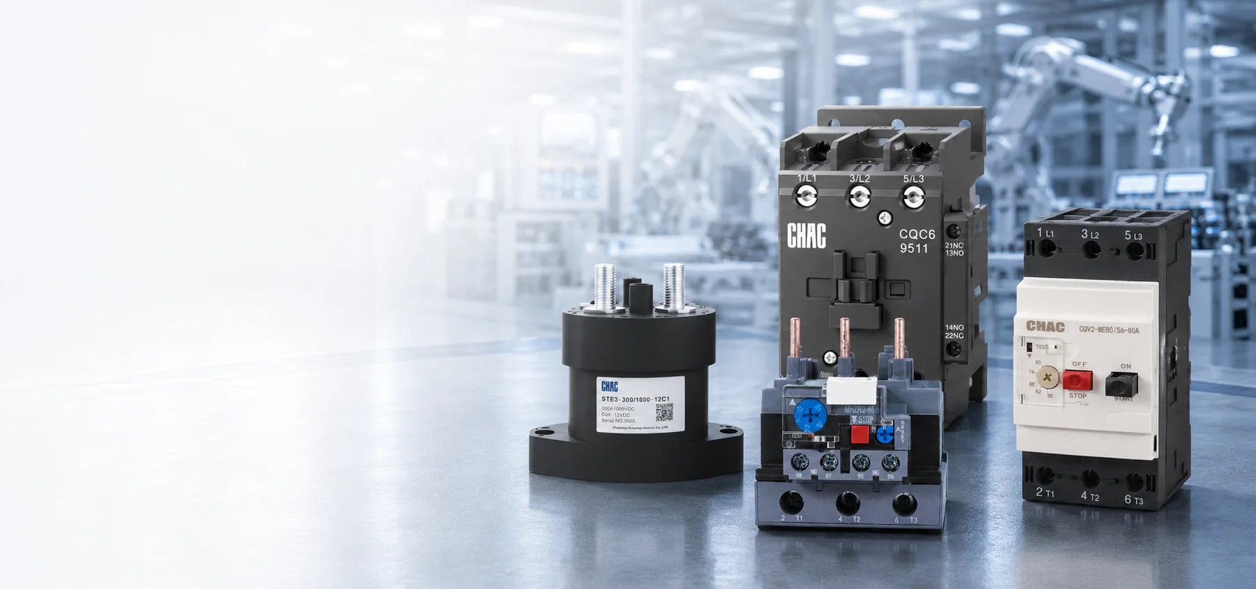
Kontaktor adalah sakelar yang dioperasikan secara elektrik dan dirancang untuk kontrol jarak jauh. Koilnya dikendalikan oleh termostat, pengontrol sistem manajemen bangunan, atau rangkaian keselamatan. Dalam desain elektromagnetik konvensional, mekanisme ini kemudian menutup kontak utama yang mengalirkan arus lebih tinggi yang dibutuhkan oleh beban. Pemisahan ini menjaga agar arus kompresor tidak masuk ke perangkat kontrol yang sensitif dan memungkinkan penerapan urutan serta interlocking secara praktis.
Gagasan dasarnya sederhana, tetapi kesalahan penggantian terjadi karena rangkaian daya dan rangkaian kontrol memiliki persyaratan yang berbeda. Tegangan yang memasok kompresor tidak harus sama dengan tegangan yang memasok koil kontaktor. Bingkai yang serupa juga dapat memiliki frekuensi koil, rating motor, kontak bantu, atau batasan lingkungan yang berbeda.
Apa Fungsi Kontaktor HVAC di Dalam Sistem?
Bagaimana kumparan mengubah sinyal kontrol menjadi gerakan mekanis?
Dalam sebuah konvensional biasanya terbuka Pada kontaktor, pegas menahan angker yang dapat bergerak agar tetap terpisah dari inti magnetik saat dalam keadaan diam. Ketika rangkaian kontrol memberikan tegangan yang ditentukan, kumparan menghasilkan fluks magnetik. Angker bergerak, tekanan kontak meningkat, dan kutub utama tertutup. Pada banyak kumparan AC konvensional, daya semu yang diperlukan saat proses penarikan berbeda dengan daya yang diperlukan setelah rangkaian magnetik terkunci; desain kumparan elektronik mungkin memiliki perilaku yang berbeda.
Perbedaan tersebut menjelaskan mengapa lembar data kumparan dapat mencantumkan baik VA arus masuk maupun VA tersegel. Trafo kontrol yang dipilih hanya berdasarkan konsumsi kondisi tunak mungkin tidak mampu mendukung pemicuan simultan dari beberapa perangkat. Keluaran kontrol elektronik juga dapat memiliki batas arus sesaat. Periksa secara tepat data kumparan dan kemampuan sumber kontrol, jangan berasumsi bahwa semua kumparan dengan tegangan yang sama memberikan beban yang sama.
Mengapa kontak utama dan kontak bantu tidak dapat dipertukarkan?
Kontak utama mengalihkan kompresor, kipas, pompa, atau rangkaian pemanas listrik. Kontak bantu membawa sinyal kontrol untuk umpan balik status, interlocking elektrik, atau urutan operasi. Keadaan normal dan ratingnya harus sesuai dengan logika awal; sebuah kontak bantu yang tampak tidak terpakai bisa jadi sangat penting bagi urutan keselamatan atau tahapan operasi. Rating arus pada kontak bantu bukanlah persetujuan untuk menggunakannya sebagai pengganti kutub beban utama. Kontaktor kompresor harus dipilih sesuai dengan tugas motor dan rangkaian kontrol peralatan tertentu. Istilah kontaktor AC dan kontaktor magnetik AC adalah sebutan umum untuk komponen saklar tersebut, bukan spesifikasi pengganti yang lengkap.
Kontaktor bukanlah perangkat proteksi yang lengkap. Proteksi beban lebih merespons arus berlebih yang berlangsung terus-menerus, sementara sekering atau pemutus sirkuit memutus arus gangguan. Fungsi-fungsi tersebut dapat berupa komponen terpisah atau terintegrasi di bagian lain dari peralatan. Panduan untuk kontaktor beban lebih dan proteksi motor menjelaskan mengapa pemutusan dan perlindungan harus dikoordinasikan, bukan diperlakukan sebagai sesuatu yang dapat saling dipertukarkan.
Bagaimana Teknisi Seharusnya Mendiagnosis Kontaktor HVAC?
Aman pemecahan masalah kontaktor mengikuti sinyal melalui rangkaian alih-alih langsung menyimpulkan dari suatu gejala ke komponen tertentu. Seorang teknisi yang berkualifikasi terlebih dahulu memastikan permintaan operasi dan status sistem keselamatan. Pemeriksaan selanjutnya menentukan apakah tegangan yang tepat mencapai kumparan dalam kondisi penarikan yang sebenarnya, apakah angker berada pada posisi yang tepat, serta apakah kontak yang tertutup memberikan tegangan yang diharapkan ke beban.
Kompartemen listrik dapat mengandung tegangan berbahaya, muatan yang tersimpan, serta peralatan bergerak otomatis. Di tempat kerja tertutup di Amerika Serikat, 1910.333 Pemilihan dan penggunaan praktik kerja mengharuskan bagian-bagian yang bertegangan agar dinonaktifkan kecuali jika pengecualian yang ditentukan berlaku. Pembatasan bagi personel yang memenuhi syarat dan tindakan perlindungan yang sesuai mengatur pekerjaan pada komponen yang bertegangan. Catatan di bawah ini merupakan logika diagnostik untuk personel terlatih, bukan prosedur kerja pada peralatan bertegangan.
| Gejala yang diamati | Bukti yang harus dikumpulkan | Keluarga kesalahan yang mungkin terjadi | Mengapa hanya penggantian saja mungkin tidak berhasil |
|---|---|---|---|
| Tidak ada tarikan saat pendinginan diminta. | Perintah kontrol, status rantai keselamatan, penandaan kumparan, dan tegangan pada kumparan | Keselamatan terbuka, gangguan kabel, kontroler gagal, koil terbuka, atau koil salah | Kontaktor mungkin tidak pernah menerima perintah yang valid. |
| Dengungan atau obrolan cepat | Tegangan sebelum dan selama proses pull-in, keluaran trafo, sambungan, dan posisi armatur | Tegangan rendah, penurunan tegangan yang berlebihan pada rangkaian, kontaminasi, hambatan mekanis, atau ketidaksesuaian frekuensi | Sebuah kumparan baru dapat bergetar di bawah suplai yang sama yang tidak stabil. |
| Koil menyala tetapi beban tidak mulai beroperasi. | Tegangan saluran, tegangan yang disalurkan melalui setiap kutub yang tertutup, status proteksi, dan kondisi beban | Kontak terbuka atau berhambatan tinggi, fase hilang, operasi proteksi, kesalahan kabel, atau beban gagal | The compressor or upstream circuit may be the root cause |
| Localized heating or discoloration | Terminal condition, conductor suitability, torque history, current balance, and contact voltage drop | Loose termination, overload, eroded contact, corrosion, or repeated chatter | Heat damage can extend into conductors and the enclosure |
| Load continues after the command ends | Coil command after shutdown, mechanical release, and isolated contact condition | Welded contacts, binding mechanism, back-fed control voltage, or logic fault | The control circuit must be ruled out before condemning the device |
Why can a normal coil-voltage reading miss a pull-in problem?
A plausible unloaded reading does not establish that the control supply can deliver the coil’s pull-in burden. A reading taken only after the armature has seated can also miss a brief voltage dip. For an authorized diagnostic test, the qualified technician records the voltage at the coil during the command, pull-in, and holding state, then compares those distinct conditions with the exact manufacturer’s operating limits. There is no universal voltage tolerance that can replace the model’s documentation.
If the voltage falls only during pull-in, the investigation shifts to the control transformer, simultaneous secondary loads, and the series devices or connections in the control path. Long conductors, poor connections, or a marginal controller output may contribute. If voltage remains within the specified limits but the armature fails to seat, mechanical condition and coil identity become more important. Neither result alone proves that the compressor is healthy.
What can contact voltage drop show that continuity cannot?
A deenergized continuity check can show that a contact closes, but it does not prove that it carries load without excessive resistance. During an authorized loaded test, the technician evaluates the voltage across each closed pole and any imbalance, using the manufacturer’s criteria where available. An abnormal result can involve contact erosion, contamination, insufficient pressure, or a damaged termination; it should be interpreted alongside load current rather than against an invented universal millivolt threshold.
The timing matters too. Coil behavior during armature movement and load-side behavior after seating are different observations. Combining them into a single statement such as “voltage is normal” can conceal a control-supply dip or a contact fault.
Can noise come from something other than damaged contacts?
Dust, insects, corrosion, or debris on magnetic faces can obstruct closure. Loose mounting and equipment vibration may amplify hum. An AC coil intended for a different frequency may not operate as specified. Inspection should therefore cover the enclosure, mechanism, mounting, coil marking, ambient conditions, and moisture evidence, not just the visible contact faces. Noise alone is not a conclusive failure test.
What Determines Contactor Life in HVAC Service?
Manufacturers distinguish mechanical life from electrical life. Mechanical-life figures describe operation without the electrical wear caused by switching the rated load. Electrical life depends on the current and voltage being switched, load type, switching duty, and operating frequency. A catalog’s largest life figure may therefore describe conditions unlike the installed HVAC duty. An air compressor contactor can also face a different start frequency and control sequence from a refrigeration compressor contactor. Compare the equipment instructions and actual switching duty before using one application as the sizing or service-life reference for the other.
Why does switching duty matter more than frame amperes?
The utilization-category framework in IEC 60947-4-1 distinguishes switching duties. AC-1 generally covers non-inductive or slightly inductive loads; AC-3 covers starting a squirrel-cage motor and switching it off while running; AC-4 covers more severe duties such as inching or plugging. A device’s AC-1 current cannot be assumed to equal its AC-3 motor rating.
For a compressor, identify the rating the equipment manufacturer actually requires. North American definite-purpose contactor documentation may specify full-load amperes, locked-rotor amperes, horsepower, or resistive-load ratings. An IEC motor rating at another voltage, or a higher resistive-current label, does not by itself establish compressor-duty suitability. Compare the exact product’s declared duty, voltage, phases, starting demands, and conditions of use with the equipment instructions.
What should be recorded when a replacement fails again?
Repeated starts, abnormal starting duration, voltage problems, and motor overload are separate stresses. Schneider Electric’s Fungsi perlindungan motor, last edited August 5, 2026, identifies rapid-cycle lockout, long-start protection, overload protection, and voltage-related protection as distinct functions. This general guidance does not prove that a particular HVAC unit includes them; its diagram and controller documentation must show what is actually implemented.
For repeat failures, retain the equipment and contactor identities, coil marking, failure time, command state, pull-in and holding observations, load-current findings, terminal condition, and relevant controller or protection events. Record whether the event follows a restart, a long idle period, simultaneous staging, or a protection operation. Comparing the failed and replacement devices with that event record is more useful than repeatedly increasing the contactor’s frame size. Compressor restart limits must come from its manufacturer, not a universal starts-per-hour rule.
Contact welding and severe pitting are outcomes, not complete diagnoses. Supply disturbances, load faults, poor terminations, chatter, and an incorrect duty rating can leave similar evidence. Correcting the original stress is part of the repair. Where the design requires separate overload protection, a relay overload termal must be selected and coordinated for the actual motor and starter; adding one is not a substitute for diagnosing a compressor fault.
When is a contact kit an acceptable repair?
Some industrial contactors have manufacturer-approved replacement coils or contact kits. Renewal can be reasonable when the exact design supports field service, the frame and arc-control parts remain undamaged, trained personnel follow the instructions, and post-service checks verify operation. The parts and device identity must remain traceable.
Complete replacement may be necessary when the housing, mechanism, coil, terminals, or arc-control parts are compromised, or when authorized renewal parts are unavailable. Filing or sanding contact faces should not be treated as an approved repair unless the manufacturer explicitly permits that procedure. A visually cleaner surface does not establish restored contact geometry or rated performance.
How Do You Specify a Compatible Replacement?
A reliable replacement starts with the equipment wiring diagram and full markings on the installed device. A photo helps identify layout but cannot verify coil burden, motor duty, or conditions of use. If markings are damaged or conflict with the diagram, consult current equipment documentation rather than guessing from appearance.
| Specification item | Apa yang harus direkam | Risk if omitted |
|---|---|---|
| Load duty | Compressor, fan, heater or pump; motor data; starting method; applicable compressor, utilization or horsepower rating | A resistive-load ampere value may be misapplied to a motor |
| Main circuit | Voltage, phase, frequency, poles, operational current, and protection arrangement | Contacts may be underrated or the switching arrangement may differ from the equipment design |
| Control circuit | Coil voltage and frequency, inrush and holding characteristics, source capacity, suppression, and terminal layout | The device may fail to pull in or exceed the controller’s output capability |
| Switching pattern | Starting frequency, operating sequence, interlocks, and auxiliary-contact states | The selected duty may not cover the installed operation |
| Installation environment | Ambient limits, enclosure, moisture, contamination, vibration, altitude, conductors, and terminals | Electrical or mechanical conditions may exceed the published limits |
| Market documentation | Destination, product standard, listing or certification scope, drawings, labels, and permitted replacement arrangements | A physically compatible part may still be unacceptable for the equipment |
The contactor must also fit the protection and isolation strategy. A disconnect may provide the designated isolation function, while a contactor provides commanded switching; neither role should be inferred solely from appearance. Review the load requirements using the same discipline described in choosing the right motor contactor. The fuse or breaker, available fault current, and equipment short-circuit rating also need their own documented review.
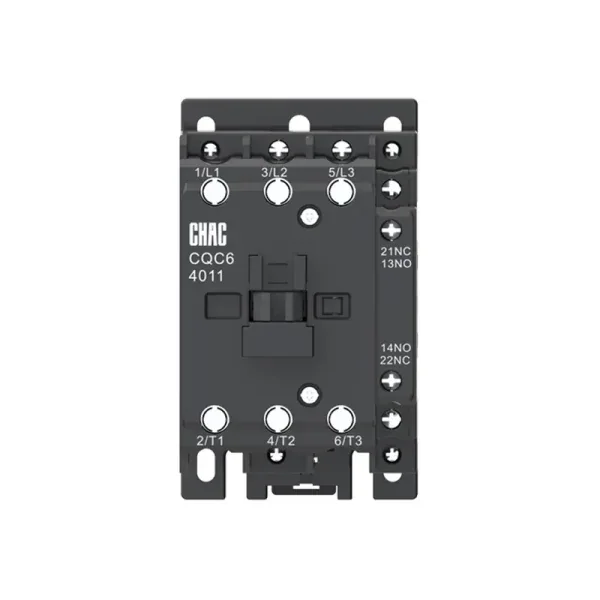
For an OEM or replacement program, approve a complete record rather than a shorthand cross-reference. A buyer evaluating an AC contactor replacement should confirm ratings for the intended voltage and duty, coil characteristics, accessories, mounting, terminal capacity, ambient limits, and required documentation. Track revisions across repeat orders so a coil or auxiliary-contact change is reviewed before it reaches the assembly line. A CHAC product-family page is a starting point for documentation, not evidence of interchangeability with an installed HVAC part.
Which Standards and Safety Rules Shape the Selection?
IEC 60947-4-1 covers electromechanical contactors and motor-starters within low-voltage switchgear and controlgear. It provides performance and verification requirements. A utilization-category designation does not itself prove third-party certification or compliance of the complete HVAC assembly.
UL 60947-4-1 addresses contactors and motor-starters with North American requirements. US installation requirements must be checked against the locally adopted electrical code, equipment instructions, and any authority having jurisdiction. An IEC rating should not be presented as an automatic substitute for the documentation required for a North American assembly.
Workplace safety is a separate obligation. Under OSHA 1910.333(b)(2), control devices and interlocks cannot be the sole means of deenergizing equipment. A thermostat set to OFF or an open contactor does not establish isolation. The qualified person must address all electrical energy sources, stored energy, lockout/tagging requirements, and verification of the deenergized condition, including possible backfeed. These are US occupational requirements; other jurisdictions have their own applicable rules.
What Are the Most Common HVAC Contactor FAQs?
What does an HVAC contactor do?
It lets a low-power control signal switch a higher-power compressor, fan, pump, or heater circuit. In a conventional electromagnetic design, the coil moves the mechanism while the main contacts carry the load current. Switching does not replace overload or short-circuit protection.
How can a technician tell whether the contactor is bad?
The qualified technician confirms the control command and coil behavior during pull-in and holding, evaluates closure and release, and checks the power delivered through the contacts. An open coil, welded contacts, or abnormal contact performance may support replacement, but control-supply, termination, protection, and load faults must also be evaluated.
Why does an HVAC contactor chatter?
Possible causes include coil undervoltage, excessive control-circuit drop, poor connections, obstructed magnetic faces, vibration, or an incorrect coil frequency. Noise alone does not identify the cause. The exact coil’s operating limits and the conditions during the event matter more than a normal reading taken at another time.
Can only the contacts be replaced?
Only when the manufacturer authorizes renewal for that design and provides the correct parts and procedure. Damage to the frame, coil, terminals, arc-control parts, or mechanism may require complete replacement. The circuit condition that caused the wear still needs investigation.
Does a replacement contactor only need the same amp rating?
No. The required coil voltage and frequency, poles, compressor or motor duty, operating frequency, auxiliary contacts, terminals, mounting, environment, and market documentation all matter. A higher resistive-current rating or similar physical size does not establish replacement suitability.
Can a contactor read the correct voltage but still fail to pull in?
Yes. An unloaded or holding-state reading may miss a brief control-voltage dip during pull-in, and a mechanical obstruction can prevent closure even with an adequate supply. Distinguishing those conditions requires model-specific data and qualified diagnosis, not homeowner testing inside an energized compartment.
Is it safe to push the contactor in manually to test the compressor?
No. Manual forcing can bypass the normal control and safety sequence and expose someone to energized parts or unexpected equipment operation. Leave internal testing to a qualified technician using the equipment instructions and applicable safe-work requirements; thermostat OFF is not verified electrical isolation.
Which Sources Support These Selection and Safety Principles?
- Komisi Elektroteknik Internasional, IEC 60947-4-1, product-standard scope and utilization categories.
- Standar dan Keterlibatan UL, UL 60947-4-1, North American contactor and motor-starter requirements.
- Schneider Electric, Fungsi perlindungan motor, updated August 5, 2026; general motor-protection guidance, not an HVAC model specification.
- Occupational Safety and Health Administration, 1910.333 Pemilihan dan penggunaan praktik kerja, US occupational electrical work requirements.
The replacement decision should start with the event and circuit requirements, not the appearance of the old part. First establish whether the command and control supply remain valid during pull-in; then evaluate the contact path, terminations, protection, and load. Select the replacement against the equipment’s required duty and exact coil data, and confirm the installation and documentation requirements before returning it to service. Repeated failure calls for finding the repeated stress, not simply increasing the ampere label. For a commercial HVAC or OEM application, the CHAC CQC6 Kontaktor HVAC product page provides a route to request model documentation and discuss the load, control, switching, and environmental requirements; it does not establish compatibility by itself.