Một contacter bị cháy có thể dường như giải thích được hiện tượng hệ thống HVAC ngừng hoạt động, nhưng việc thay thế nó vẫn chưa xác định được nguyên nhân gây ra sự cố. Nguồn điều khiển không ổn định, đầu nối bị hư hỏng, chế độ đóng cắt không phù hợp hoặc lỗi của máy nén đều có thể gây ứng suất lên thiết bị thay thế theo cùng một cách. Câu hỏi quan trọng cần đặt ra là liệu thiết bị có nhận được lệnh hợp lệ, đóng mạch đúng cách và cung cấp điện cho tải đang hoạt động bình thường hay không. Đây là những kiểm tra riêng biệt; nếu nhầm lẫn giữa chúng, có thể dẫn đến chi phí thay thế linh kiện lặp lại và thời gian ngừng hoạt động kéo dài. Tài liệu hướng dẫn này giải thích chức năng của contacter, cách các kỹ thuật viên có trình độ phân biệt giữa lỗi điều khiển với lỗi tiếp điểm và lỗi tải, cũng như các tài liệu hỗ trợ quyết định thay thế thiết bị.
Câu trả lời ngắn gọn là một công tắc tơ HVAC cho phép mạch điều khiển công suất thấp chuyển mạch cho mạch của máy nén, quạt dàn ngưng, bộ gia nhiệt hoặc bơm. Việc chẩn đoán đáng tin cậy đòi hỏi phải tách biệt tín hiệu điều khiển cuộn dây khỏi tiếp điểm và phản ứng của tải. Linh kiện thay thế cần phải phù hợp với điện áp và tần số đã được xác minh của cuộn dây, cách bố trí cực, định mức chịu tải, tốc độ đóng cắt, các đầu nối và môi trường hoạt động. IEC 60947-4-1 cung cấp một khung tiêu chuẩn sản phẩm cho công tắc tơ và thiết bị khởi động động cơ, chứ không phải bằng chứng rằng bất kỳ linh kiện thay thế cụ thể nào đều phù hợp với thiết bị. Hãy để kỹ thuật viên có trình độ ghi lại các yêu cầu của mạch đang lắp trước khi chọn linh kiện; chỉ đơn thuần chọn linh kiện có cùng giá trị ampe là chưa đủ.
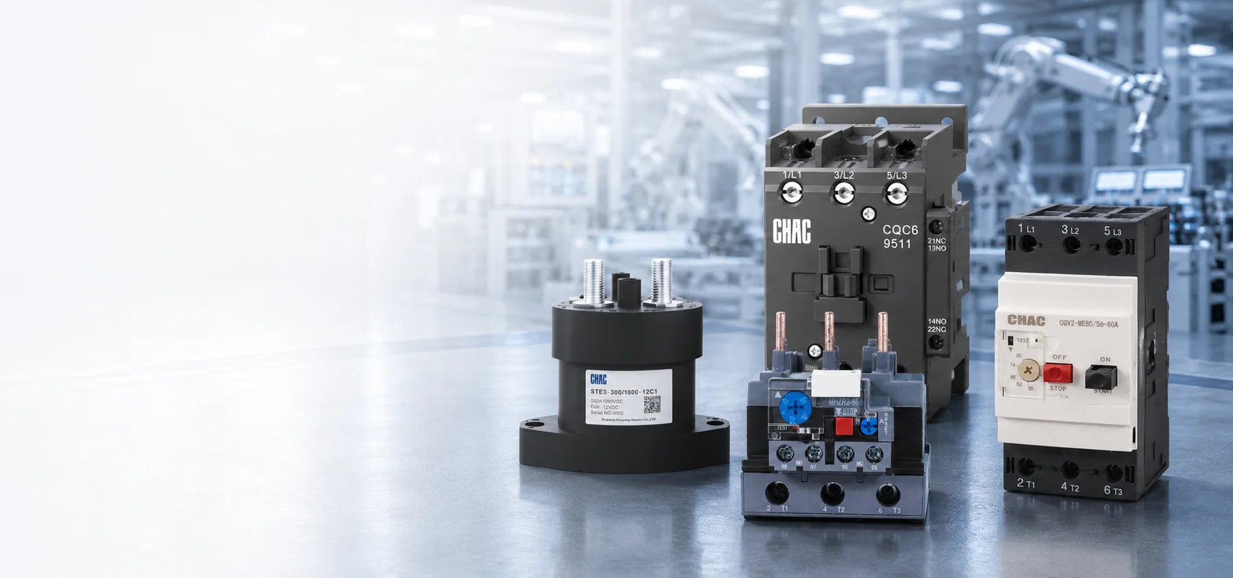
Contactor là một thiết bị đóng cắt được điều khiển bằng điện, được thiết kế để vận hành từ xa. Cuộn dây của nó được kích hoạt bởi thermostat, bộ điều khiển hệ thống tòa nhà hoặc mạch an toàn. Trong cấu trúc điện từ truyền thống, cơ cấu này sẽ đóng các tiếp điểm chính, qua đó dẫn dòng điện lớn hơn cần thiết cho tải. Sự tách biệt này giúp ngăn dòng điện của máy nén không đi vào các thiết bị điều khiển nhạy cảm, đồng thời tạo điều kiện thuận lợi cho việc lập trình thứ tự hoạt động và liên động.
Ý tưởng cơ bản rất đơn giản, nhưng các lỗi thay thế vẫn xảy ra vì mạch nguồn và mạch điều khiển có những yêu cầu khác nhau. Điện áp cấp cho máy nén không nhất thiết phải là điện áp cấp cho… Cuộn dây tiếp xúc. Các khung tương tự cũng có thể có tần số cuộn dây, công suất động cơ, tiếp điểm phụ hoặc các giới hạn môi trường khác nhau.
Contactor HVAC trong hệ thống có chức năng gì?
Cuộn dây biến tín hiệu điều khiển thành chuyển động cơ học như thế nào?
Trong một cách thông thường thường mở Trong công tắc tơ, lò xo giữ phần mạch động cách xa lõi từ khi ở trạng thái nghỉ. Khi mạch điều khiển cấp điện áp định mức, cuộn dây tạo ra từ thông. Phần mạch động di chuyển, lực ép tiếp điểm tăng lên và các cực chính đóng lại. Đối với nhiều loại cuộn dây AC thông thường, công suất biểu kiến cần thiết trong quá trình hút vào khác với công suất cần thiết sau khi mạch từ đã được kín; các thiết kế cuộn dây điện tử có thể hoạt động theo cách khác.
Sự khác biệt này giải thích tại sao một bảng thông số kỹ thuật của cuộn dây có thể ghi cả công suất VA khi khởi động và công suất VA ở trạng thái ổn định. Một máy biến áp điều khiển được lựa chọn chỉ dựa trên mức tiêu thụ ở chế độ ổn định có thể không đủ để hỗ trợ việc đóng đồng thời nhiều thiết bị. Các đầu ra điều khiển điện tử cũng có thể có giới hạn dòng điện tức thời. Hãy kiểm tra chính xác các thông số của cuộn dây và khả năng cung cấp nguồn của mạch điều khiển thay vì mặc định rằng tất cả các cuộn dây cùng điện áp đều gây ra cùng một tải như nhau.
Tại sao tiếp điểm chính và tiếp điểm phụ không thể thay thế cho nhau?
Các tiếp điểm chính đóng cắt mạch của máy nén, quạt, bơm hoặc mạch sưởi điện. Các tiếp điểm phụ truyền tín hiệu điều khiển để phản hồi trạng thái, liên động điện hoặc điều khiển theo trình tự. Trạng thái thường hở và các thông số định mức của chúng phải phù hợp với logic ban đầu; một tiếp điểm phụ tưởng chừng không sử dụng thực ra có thể rất quan trọng đối với chu trình an toàn hoặc điều khiển theo bậc. Dòng điện định mức của tiếp điểm phụ không được coi là cơ sở để thay thế cho cực tải chính. Contactor máy nén phải được lựa chọn sao cho phù hợp với chế độ làm việc của động cơ và mạch điều khiển của thiết bị cụ thể. “Contactor điều hòa” và “contactor từ điều hòa” là những cách gọi phổ biến dành cho bộ phận đóng cắt này, nhưng chúng không phải là các thông số kỹ thuật thay thế hoàn chỉnh.
Contactor không phải là một thiết bị bảo vệ hoàn chỉnh. Chức năng bảo vệ quá tải phản ứng với dòng điện vượt mức kéo dài, trong khi cầu chì hoặc aptomat sẽ ngắt dòng điện sự cố. Các chức năng này có thể được tách riêng hoặc tích hợp ở các bộ phận khác của thiết bị. Hướng dẫn về Contactor quá tải và bảo vệ động cơ giải thích lý do tại sao việc chuyển mạch và bảo vệ phải được phối hợp thay vì được coi là có thể thay thế cho nhau.
Kỹ thuật viên nên chẩn đoán một công tắc tơ HVAC như thế nào?
An toàn xử lý sự cố công tắc tơ Thiết bị theo dõi tín hiệu xuyên suốt mạch điện thay vì chỉ dựa vào một triệu chứng để phán đoán linh kiện bị lỗi. Một kỹ thuật viên có trình độ trước tiên sẽ xác nhận tín hiệu điều khiển hoạt động và trạng thái của các mạch an toàn. Các bước kiểm tra tiếp theo nhằm xác định xem cuộn dây có nhận được điện áp đúng như yêu cầu trong điều kiện đóng mạch thực tế hay không, phần lõi sắt di động có đóng khít hoàn toàn hay không, và các tiếp điểm đã đóng có cung cấp điện áp mong đợi đến tải hay không.
Các ngăn điện có thể chứa điện áp nguy hiểm, điện tích tích trữ và các thiết bị chuyển động tự động. Tại các nơi làm việc được che chắn ở Hoa Kỳ, 1910.333 Lựa chọn và sử dụng các phương pháp làm việc Yêu cầu các bộ phận mang điện hở phải được ngắt nguồn, trừ khi có các trường hợp ngoại lệ được quy định. Các công việc trên các bộ phận đang mang điện phải tuân theo những hạn chế đối với người có trình độ chuyên môn và áp dụng các biện pháp bảo vệ phù hợp. Những nhận xét dưới đây là logic chẩn đoán dành cho nhân viên đã được đào tạo, chứ không phải là quy trình làm việc khi đang có điện.
| Triệu chứng được quan sát thấy | Bằng chứng cần thu thập | Các họ lỗi có thể xảy ra | Tại sao chỉ riêng việc thay thế có thể không hiệu quả |
|---|---|---|---|
| Không có hiện tượng hút vào khi yêu cầu làm mát | Lệnh điều khiển, trạng thái mạch an toàn, ký hiệu cuộn dây và điện áp trên cuộn dây | An toàn mở, lỗi dây điện, bộ điều khiển bị hỏng, cuộn dây hở mạch hoặc cuộn dây sai | Rơ-le điều khiển có thể không bao giờ nhận được lệnh hợp lệ. |
| Tiếng vo ve hoặc tiếng nói chuyện rộn ràng | Điện áp trước và trong quá trình đóng mạch, đầu ra của máy biến áp, các kết nối và vị trí đặt phần ứng | Điện áp thấp, sụt áp mạch quá mức, nhiễm bẩn, tắc nghẽn cơ học hoặc sai lệch tần số | Một cuộn dây mới vẫn có thể bị rung lắc dưới cùng một nguồn điện không ổn định. |
| Cuộn dây hút nhưng tải không khởi động. | Điện áp đường dây, điện áp được cung cấp qua mỗi cực đóng, trạng thái bảo vệ và tình trạng tải | Tiếp điểm hở hoặc có điện trở cao, mất pha, bảo vệ hoạt động, lỗi nối dây hoặc tải bị hỏng | Máy nén hoặc mạch phía trên nguồn có thể là nguyên nhân gốc rễ. |
| Sự nóng lên cục bộ hoặc đổi màu | Tình trạng đầu cuối, độ phù hợp của dây dẫn, lịch sử mô-men xoắn, sự cân bằng dòng điện và sụt áp tiếp xúc | Đoạn mạch hở, quá tải, tiếp xúc bị mài mòn, ăn mòn hoặc chập chờn liên tục | Thiệt hại do nhiệt có thể lan vào các dây dẫn và vỏ bọc. |
| Tải tiếp tục sau khi lệnh kết thúc. | Lệnh cuộn dây sau khi tắt máy, thao tác nhả cơ khí và trạng thái tiếp điểm cách ly | Welded contacts, binding mechanism, back-fed control voltage, or logic fault | The control circuit must be ruled out before condemning the device |
Why can a normal coil-voltage reading miss a pull-in problem?
A plausible unloaded reading does not establish that the control supply can deliver the coil’s pull-in burden. A reading taken only after the armature has seated can also miss a brief voltage dip. For an authorized diagnostic test, the qualified technician records the voltage at the coil during the command, pull-in, and holding state, then compares those distinct conditions with the exact manufacturer’s operating limits. There is no universal voltage tolerance that can replace the model’s documentation.
If the voltage falls only during pull-in, the investigation shifts to the control transformer, simultaneous secondary loads, and the series devices or connections in the control path. Long conductors, poor connections, or a marginal controller output may contribute. If voltage remains within the specified limits but the armature fails to seat, mechanical condition and coil identity become more important. Neither result alone proves that the compressor is healthy.
What can contact voltage drop show that continuity cannot?
A deenergized continuity check can show that a contact closes, but it does not prove that it carries load without excessive resistance. During an authorized loaded test, the technician evaluates the voltage across each closed pole and any imbalance, using the manufacturer’s criteria where available. An abnormal result can involve contact erosion, contamination, insufficient pressure, or a damaged termination; it should be interpreted alongside load current rather than against an invented universal millivolt threshold.
The timing matters too. Coil behavior during armature movement and load-side behavior after seating are different observations. Combining them into a single statement such as “voltage is normal” can conceal a control-supply dip or a contact fault.
Can noise come from something other than damaged contacts?
Dust, insects, corrosion, or debris on magnetic faces can obstruct closure. Loose mounting and equipment vibration may amplify hum. An AC coil intended for a different frequency may not operate as specified. Inspection should therefore cover the enclosure, mechanism, mounting, coil marking, ambient conditions, and moisture evidence, not just the visible contact faces. Noise alone is not a conclusive failure test.
What Determines Contactor Life in HVAC Service?
Manufacturers distinguish mechanical life from electrical life. Mechanical-life figures describe operation without the electrical wear caused by switching the rated load. Electrical life depends on the current and voltage being switched, load type, switching duty, and operating frequency. A catalog’s largest life figure may therefore describe conditions unlike the installed HVAC duty. An air compressor contactor can also face a different start frequency and control sequence from a refrigeration compressor contactor. Compare the equipment instructions and actual switching duty before using one application as the sizing or service-life reference for the other.
Why does switching duty matter more than frame amperes?
The utilization-category framework in IEC 60947-4-1 distinguishes switching duties. AC-1 generally covers non-inductive or slightly inductive loads; AC-3 covers starting a squirrel-cage motor and switching it off while running; AC-4 covers more severe duties such as inching or plugging. A device’s AC-1 current cannot be assumed to equal its AC-3 motor rating.
For a compressor, identify the rating the equipment manufacturer actually requires. North American definite-purpose contactor documentation may specify full-load amperes, locked-rotor amperes, horsepower, or resistive-load ratings. An IEC motor rating at another voltage, or a higher resistive-current label, does not by itself establish compressor-duty suitability. Compare the exact product’s declared duty, voltage, phases, starting demands, and conditions of use with the equipment instructions.
What should be recorded when a replacement fails again?
Repeated starts, abnormal starting duration, voltage problems, and motor overload are separate stresses. Schneider Electric’s Chức năng bảo vệ động cơ, last edited August 5, 2026, identifies rapid-cycle lockout, long-start protection, overload protection, and voltage-related protection as distinct functions. This general guidance does not prove that a particular HVAC unit includes them; its diagram and controller documentation must show what is actually implemented.
For repeat failures, retain the equipment and contactor identities, coil marking, failure time, command state, pull-in and holding observations, load-current findings, terminal condition, and relevant controller or protection events. Record whether the event follows a restart, a long idle period, simultaneous staging, or a protection operation. Comparing the failed and replacement devices with that event record is more useful than repeatedly increasing the contactor’s frame size. Compressor restart limits must come from its manufacturer, not a universal starts-per-hour rule.
Contact welding and severe pitting are outcomes, not complete diagnoses. Supply disturbances, load faults, poor terminations, chatter, and an incorrect duty rating can leave similar evidence. Correcting the original stress is part of the repair. Where the design requires separate overload protection, a Rơle quá tải nhiệt must be selected and coordinated for the actual motor and starter; adding one is not a substitute for diagnosing a compressor fault.
When is a contact kit an acceptable repair?
Some industrial contactors have manufacturer-approved replacement coils or contact kits. Renewal can be reasonable when the exact design supports field service, the frame and arc-control parts remain undamaged, trained personnel follow the instructions, and post-service checks verify operation. The parts and device identity must remain traceable.
Complete replacement may be necessary when the housing, mechanism, coil, terminals, or arc-control parts are compromised, or when authorized renewal parts are unavailable. Filing or sanding contact faces should not be treated as an approved repair unless the manufacturer explicitly permits that procedure. A visually cleaner surface does not establish restored contact geometry or rated performance.
How Do You Specify a Compatible Replacement?
A reliable replacement starts with the equipment wiring diagram and full markings on the installed device. A photo helps identify layout but cannot verify coil burden, motor duty, or conditions of use. If markings are damaged or conflict with the diagram, consult current equipment documentation rather than guessing from appearance.
| Specification item | What to record | Risk if omitted |
|---|---|---|
| Load duty | Compressor, fan, heater or pump; motor data; starting method; applicable compressor, utilization or horsepower rating | A resistive-load ampere value may be misapplied to a motor |
| Main circuit | Voltage, phase, frequency, poles, operational current, and protection arrangement | Contacts may be underrated or the switching arrangement may differ from the equipment design |
| Control circuit | Coil voltage and frequency, inrush and holding characteristics, source capacity, suppression, and terminal layout | The device may fail to pull in or exceed the controller’s output capability |
| Switching pattern | Starting frequency, operating sequence, interlocks, and auxiliary-contact states | The selected duty may not cover the installed operation |
| Installation environment | Ambient limits, enclosure, moisture, contamination, vibration, altitude, conductors, and terminals | Electrical or mechanical conditions may exceed the published limits |
| Bản ghi thị trường | Destination, product standard, listing or certification scope, drawings, labels, and permitted replacement arrangements | A physically compatible part may still be unacceptable for the equipment |
The contactor must also fit the protection and isolation strategy. A disconnect may provide the designated isolation function, while a contactor provides commanded switching; neither role should be inferred solely from appearance. Review the load requirements using the same discipline described in choosing the right motor contactor. The fuse or breaker, available fault current, and equipment short-circuit rating also need their own documented review.
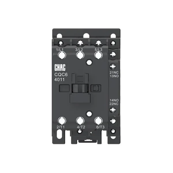
For an OEM or replacement program, approve a complete record rather than a shorthand cross-reference. A buyer evaluating an AC contactor replacement should confirm ratings for the intended voltage and duty, coil characteristics, accessories, mounting, terminal capacity, ambient limits, and required documentation. Track revisions across repeat orders so a coil or auxiliary-contact change is reviewed before it reaches the assembly line. A CHAC product-family page is a starting point for documentation, not evidence of interchangeability with an installed HVAC part.
Which Standards and Safety Rules Shape the Selection?
IEC 60947-4-1 covers electromechanical contactors and motor-starters within low-voltage switchgear and controlgear. It provides performance and verification requirements. A utilization-category designation does not itself prove third-party certification or compliance of the complete HVAC assembly.
UL 60947-4-1 addresses contactors and motor-starters with North American requirements. US installation requirements must be checked against the locally adopted electrical code, equipment instructions, and any authority having jurisdiction. An IEC rating should not be presented as an automatic substitute for the documentation required for a North American assembly.
Workplace safety is a separate obligation. Under OSHA 1910.333(b)(2), control devices and interlocks cannot be the sole means of deenergizing equipment. A thermostat set to OFF or an open contactor does not establish isolation. The qualified person must address all electrical energy sources, stored energy, lockout/tagging requirements, and verification of the deenergized condition, including possible backfeed. These are US occupational requirements; other jurisdictions have their own applicable rules.
What Are the Most Common HVAC Contactor FAQs?
What does an HVAC contactor do?
It lets a low-power control signal switch a higher-power compressor, fan, pump, or heater circuit. In a conventional electromagnetic design, the coil moves the mechanism while the main contacts carry the load current. Switching does not replace overload or short-circuit protection.
How can a technician tell whether the contactor is bad?
The qualified technician confirms the control command and coil behavior during pull-in and holding, evaluates closure and release, and checks the power delivered through the contacts. An open coil, welded contacts, or abnormal contact performance may support replacement, but control-supply, termination, protection, and load faults must also be evaluated.
Why does an HVAC contactor chatter?
Possible causes include coil undervoltage, excessive control-circuit drop, poor connections, obstructed magnetic faces, vibration, or an incorrect coil frequency. Noise alone does not identify the cause. The exact coil’s operating limits and the conditions during the event matter more than a normal reading taken at another time.
Can only the contacts be replaced?
Only when the manufacturer authorizes renewal for that design and provides the correct parts and procedure. Damage to the frame, coil, terminals, arc-control parts, or mechanism may require complete replacement. The circuit condition that caused the wear still needs investigation.
Does a replacement contactor only need the same amp rating?
No. The required coil voltage and frequency, poles, compressor or motor duty, operating frequency, auxiliary contacts, terminals, mounting, environment, and market documentation all matter. A higher resistive-current rating or similar physical size does not establish replacement suitability.
Can a contactor read the correct voltage but still fail to pull in?
Yes. An unloaded or holding-state reading may miss a brief control-voltage dip during pull-in, and a mechanical obstruction can prevent closure even with an adequate supply. Distinguishing those conditions requires model-specific data and qualified diagnosis, not homeowner testing inside an energized compartment.
Is it safe to push the contactor in manually to test the compressor?
No. Manual forcing can bypass the normal control and safety sequence and expose someone to energized parts or unexpected equipment operation. Leave internal testing to a qualified technician using the equipment instructions and applicable safe-work requirements; thermostat OFF is not verified electrical isolation.
Which Sources Support These Selection and Safety Principles?
- Ủy ban Kỹ thuật Điện Quốc tế, IEC 60947-4-1, product-standard scope and utilization categories.
- Tiêu chuẩn và Sự tham gia của UL, UL 60947-4-1, North American contactor and motor-starter requirements.
- Schneider Electric, Chức năng bảo vệ động cơ, updated August 5, 2026; general motor-protection guidance, not an HVAC model specification.
- Occupational Safety and Health Administration, 1910.333 Lựa chọn và sử dụng các phương pháp làm việc, US occupational electrical work requirements.
The replacement decision should start with the event and circuit requirements, not the appearance of the old part. First establish whether the command and control supply remain valid during pull-in; then evaluate the contact path, terminations, protection, and load. Select the replacement against the equipment’s required duty and exact coil data, and confirm the installation and documentation requirements before returning it to service. Repeated failure calls for finding the repeated stress, not simply increasing the ampere label. For a commercial HVAC or OEM application, the CHAC CQC6 Contactor HVAC product page provides a route to request model documentation and discuss the load, control, switching, and environmental requirements; it does not establish compatibility by itself.