Um contator queimado pode parecer explicar uma parada do sistema HVAC, mas substituí-lo não esclarece o motivo da falha. Uma fonte de alimentação de controle instável, terminais danificados, uma aplicação de comutação inadequada ou uma falha no compressor podem sobrecarregar o contator de reposição da mesma forma. A pergunta relevante é se o dispositivo recebe um comando válido, fecha corretamente e fornece energia a uma carga em boas condições de funcionamento. Esses são testes distintos, e confundi-los pode resultar em custos recorrentes com peças e em períodos de inatividade. Este guia explica a função do contator, como técnicos qualificados distinguem falhas no circuito de comando das falhas nos contatos e na carga, e quais documentos devem fundamentar a decisão de substituição.
A resposta curta é que um contator HVAC permite que um circuito de controle de baixa potência comute um compressor, ventilador do condensador, aquecedor ou circuito de bomba. Um diagnóstico confiável separa o comando da bobina da resposta dos contatos e da carga. Uma peça de reposição deve corresponder à tensão e frequência verificadas da bobina, ao arranjo de polos, à classificação de carga e serviço, à taxa de comutação, aos terminais e ao ambiente. A IEC 60947-4-1 fornece uma estrutura padrão para produtos de contatores e partidas de motores, mas não é uma prova de que qualquer peça de reposição específica seja adequada ao equipamento. Peça a um técnico qualificado registrar os requisitos do circuito instalado antes de selecionar uma peça; apenas um número de amperes correspondente não é suficiente.
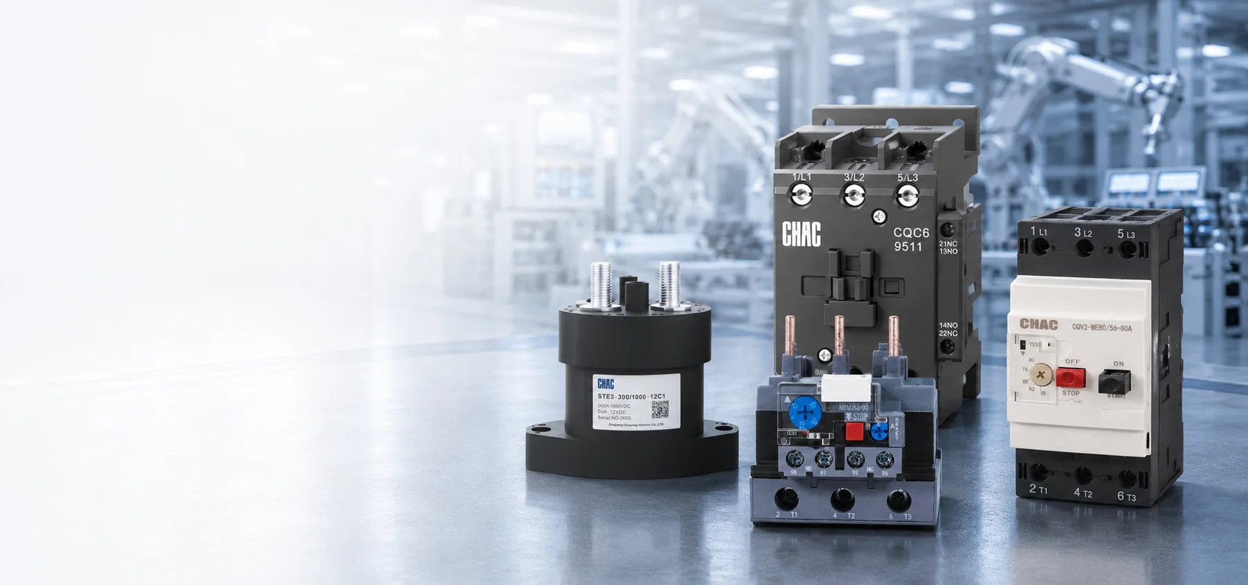
Um contatores é um interruptor acionado eletricamente, projetado para controle remoto. Um termostato, um controlador de gerenciamento de edifícios ou uma cadeia de segurança comanda sua bobina. Em um projeto eletromagnético convencional, o mecanismo então fecha os contatos principais que conduzem a corrente mais alta exigida pela carga. Essa separação mantém a corrente do compressor afastada dos dispositivos de controle sensíveis e torna viáveis a sequenciamento e o intertravamento.
A ideia básica é simples, mas ocorrem erros de substituição porque o circuito de potência e o circuito de controle têm requisitos diferentes. A tensão que alimenta o compressor não precisa ser a mesma que alimenta seu bobina do contatores. Quadros semelhantes também podem apresentar frequências de bobina, classificações de motor, contatos auxiliares ou limites ambientais diferentes.
O que faz um contator de HVAC dentro do sistema?
Como a bobina transforma um sinal de controle em movimento mecânico?
Em um convencional normalmente aberto No contator, uma mola mantém a armadura móvel afastada do núcleo magnético em repouso. Quando o circuito de comando aplica a tensão especificada, a bobina gera fluxo magnético. A armadura desloca-se, a pressão de contato aumenta e os polos principais fecham. Para muitas bobinas convencionais de corrente alternada, a potência aparente necessária durante a atracação difere daquela requerida após o circuito magnético estar fechado; projetos de bobinas eletrônicas podem apresentar comportamento diferente.
Essa distinção explica por que uma folha de dados de bobina pode listar tanto a potência aparente de inrush quanto a potência aparente em estado estacionário. Um transformador de controle selecionado apenas com base no consumo em regime permanente pode não suportar o acionamento simultâneo de vários dispositivos. As saídas de controle eletrônicas também podem ter limites de corrente momentânea. Verifique os dados exatos da bobina e a capacidade da fonte de alimentação do controle, em vez de presumir que todas as bobinas da mesma tensão imponham a mesma carga.
Por que os contatos principais e auxiliares não são intercambiáveis?
Os contatos principais comutam o compressor, o ventilador, a bomba ou o circuito de aquecimento elétrico. Os contatos auxiliares transmitem sinais de controle para feedback de estado, intertravamento elétrico ou sequenciamento. Seu estado normal e suas classificações devem corresponder à lógica original; um contato auxiliar aparentemente não utilizado pode ser essencial para uma sequência de segurança ou de etapas. A classificação de corrente de um contato auxiliar não autoriza seu uso em substituição a um polo de carga principal. Um contator de compressor deve ser selecionado de acordo com a classe de serviço do motor do equipamento específico e com o circuito de comando. “Contator de ar-condicionado” e “contator magnético de ar-condicionado” são descrições comuns desse componente de comutação, e não especificações completas para sua substituição.
Um contatores não é um dispositivo de proteção completo. A proteção contra sobrecarga reage a uma sobrecorrente prolongada, enquanto um fusível ou disjuntor interrompe a corrente de falta. Essas funções podem estar separadas ou integradas em outros componentes do equipamento. O guia para contatores de sobrecarga e proteção de motores explica por que a comutação e a proteção devem ser coordenadas, em vez de tratadas como intercambiáveis.
Como os técnicos devem diagnosticar um contator de HVAC?
Seguro Resolução de problemas em contatores Segue o sinal ao longo do circuito, em vez de pular diretamente de um sintoma para uma peça. Um técnico qualificado primeiro confirma o comando de operação e o estado dos dispositivos de segurança. As verificações seguintes determinam se a tensão correta chega à bobina na condição real de acionamento, se a armadura assenta corretamente e se os contatos fechados fornecem a tensão esperada à carga.
Compartimentos elétricos podem conter tensões perigosas, carga armazenada e equipamentos móveis automáticos. Em locais de trabalho cobertos nos EUA, 1910.333 Seleção e utilização de práticas de trabalho Exige que as partes vivas expostas sejam desenergizadas, salvo quando se aplicarem as exceções especificadas. Restrições para pessoas qualificadas e medidas de proteção adequadas regem os trabalhos em partes energizadas. As observações a seguir constituem uma lógica de diagnóstico destinada ao pessoal treinado e não representam um procedimento de trabalho sob tensão.
| Sintoma observado | Evidências a serem coletadas | Famílias de falhas possíveis | Por que a substituição por si só pode falhar |
|---|---|---|---|
| Nenhum acionamento quando o resfriamento é solicitado | Comando de controle, estado da cadeia de segurança, marcação da bobina e tensão na bobina | Segurança aberta, falha na fiação, controlador com defeito, bobina aberta ou bobina incorreta | O contato pode nunca receber um comando válido. |
| Zumbido ou tagarelice rápida | Tensão antes e durante a atracação, saída do transformador, conexões e assentamento da armadura | Baixa tensão, queda de tensão excessiva no circuito, contaminação, obstrução mecânica ou desalinhamento de frequência | Uma nova bobina pode apresentar vibração sob a mesma alimentação instável. |
| A bobina atrai, mas a carga não inicia. | Tensão de linha, tensão fornecida por cada polo fechado, estado de proteção e condição de carga | Contato aberto ou de alta resistência, perda de fase, operação do dispositivo de proteção, falha na fiação ou carga defeituosa | O compressor ou o circuito a montante pode ser a causa raiz. |
| Aquecimento localizado ou descoloração | Terminal condition, conductor suitability, torque history, current balance, and contact voltage drop | Loose termination, overload, eroded contact, corrosion, or repeated chatter | Heat damage can extend into conductors and the enclosure |
| Load continues after the command ends | Coil command after shutdown, mechanical release, and isolated contact condition | Welded contacts, binding mechanism, back-fed control voltage, or logic fault | The control circuit must be ruled out before condemning the device |
Why can a normal coil-voltage reading miss a pull-in problem?
A plausible unloaded reading does not establish that the control supply can deliver the coil’s pull-in burden. A reading taken only after the armature has seated can also miss a brief voltage dip. For an authorized diagnostic test, the qualified technician records the voltage at the coil during the command, pull-in, and holding state, then compares those distinct conditions with the exact manufacturer’s operating limits. There is no universal voltage tolerance that can replace the model’s documentation.
If the voltage falls only during pull-in, the investigation shifts to the control transformer, simultaneous secondary loads, and the series devices or connections in the control path. Long conductors, poor connections, or a marginal controller output may contribute. If voltage remains within the specified limits but the armature fails to seat, mechanical condition and coil identity become more important. Neither result alone proves that the compressor is healthy.
What can contact voltage drop show that continuity cannot?
A deenergized continuity check can show that a contact closes, but it does not prove that it carries load without excessive resistance. During an authorized loaded test, the technician evaluates the voltage across each closed pole and any imbalance, using the manufacturer’s criteria where available. An abnormal result can involve contact erosion, contamination, insufficient pressure, or a damaged termination; it should be interpreted alongside load current rather than against an invented universal millivolt threshold.
The timing matters too. Coil behavior during armature movement and load-side behavior after seating are different observations. Combining them into a single statement such as “voltage is normal” can conceal a control-supply dip or a contact fault.
Can noise come from something other than damaged contacts?
Dust, insects, corrosion, or debris on magnetic faces can obstruct closure. Loose mounting and equipment vibration may amplify hum. An AC coil intended for a different frequency may not operate as specified. Inspection should therefore cover the enclosure, mechanism, mounting, coil marking, ambient conditions, and moisture evidence, not just the visible contact faces. Noise alone is not a conclusive failure test.
What Determines Contactor Life in HVAC Service?
Manufacturers distinguish mechanical life from electrical life. Mechanical-life figures describe operation without the electrical wear caused by switching the rated load. Electrical life depends on the current and voltage being switched, load type, switching duty, and operating frequency. A catalog’s largest life figure may therefore describe conditions unlike the installed HVAC duty. An air compressor contactor can also face a different start frequency and control sequence from a refrigeration compressor contactor. Compare the equipment instructions and actual switching duty before using one application as the sizing or service-life reference for the other.
Why does switching duty matter more than frame amperes?
The utilization-category framework in IEC 60947-4-1 distinguishes switching duties. AC-1 generally covers non-inductive or slightly inductive loads; AC-3 covers starting a squirrel-cage motor and switching it off while running; AC-4 covers more severe duties such as inching or plugging. A device’s AC-1 current cannot be assumed to equal its AC-3 motor rating.
For a compressor, identify the rating the equipment manufacturer actually requires. North American definite-purpose contactor documentation may specify full-load amperes, locked-rotor amperes, horsepower, or resistive-load ratings. An IEC motor rating at another voltage, or a higher resistive-current label, does not by itself establish compressor-duty suitability. Compare the exact product’s declared duty, voltage, phases, starting demands, and conditions of use with the equipment instructions.
What should be recorded when a replacement fails again?
Repeated starts, abnormal starting duration, voltage problems, and motor overload are separate stresses. Schneider Electric’s Funções de proteção do motor, last edited August 5, 2026, identifies rapid-cycle lockout, long-start protection, overload protection, and voltage-related protection as distinct functions. This general guidance does not prove that a particular HVAC unit includes them; its diagram and controller documentation must show what is actually implemented.
For repeat failures, retain the equipment and contactor identities, coil marking, failure time, command state, pull-in and holding observations, load-current findings, terminal condition, and relevant controller or protection events. Record whether the event follows a restart, a long idle period, simultaneous staging, or a protection operation. Comparing the failed and replacement devices with that event record is more useful than repeatedly increasing the contactor’s frame size. Compressor restart limits must come from its manufacturer, not a universal starts-per-hour rule.
Contact welding and severe pitting are outcomes, not complete diagnoses. Supply disturbances, load faults, poor terminations, chatter, and an incorrect duty rating can leave similar evidence. Correcting the original stress is part of the repair. Where the design requires separate overload protection, a relé de sobrecarga térmica must be selected and coordinated for the actual motor and starter; adding one is not a substitute for diagnosing a compressor fault.
When is a contact kit an acceptable repair?
Some industrial contactors have manufacturer-approved replacement coils or contact kits. Renewal can be reasonable when the exact design supports field service, the frame and arc-control parts remain undamaged, trained personnel follow the instructions, and post-service checks verify operation. The parts and device identity must remain traceable.
Complete replacement may be necessary when the housing, mechanism, coil, terminals, or arc-control parts are compromised, or when authorized renewal parts are unavailable. Filing or sanding contact faces should not be treated as an approved repair unless the manufacturer explicitly permits that procedure. A visually cleaner surface does not establish restored contact geometry or rated performance.
How Do You Specify a Compatible Replacement?
A reliable replacement starts with the equipment wiring diagram and full markings on the installed device. A photo helps identify layout but cannot verify coil burden, motor duty, or conditions of use. If markings are damaged or conflict with the diagram, consult current equipment documentation rather than guessing from appearance.
| Specification item | What to record | Risk if omitted |
|---|---|---|
| Carga útil | Compressor, fan, heater or pump; motor data; starting method; applicable compressor, utilization or horsepower rating | A resistive-load ampere value may be misapplied to a motor |
| Circuito principal | Voltage, phase, frequency, poles, operational current, and protection arrangement | Contacts may be underrated or the switching arrangement may differ from the equipment design |
| Control circuit | Coil voltage and frequency, inrush and holding characteristics, source capacity, suppression, and terminal layout | The device may fail to pull in or exceed the controller’s output capability |
| Switching pattern | Starting frequency, operating sequence, interlocks, and auxiliary-contact states | The selected duty may not cover the installed operation |
| Ambiente de instalação | Ambient limits, enclosure, moisture, contamination, vibration, altitude, conductors, and terminals | Electrical or mechanical conditions may exceed the published limits |
| Market documentation | Destination, product standard, listing or certification scope, drawings, labels, and permitted replacement arrangements | A physically compatible part may still be unacceptable for the equipment |
The contactor must also fit the protection and isolation strategy. A disconnect may provide the designated isolation function, while a contactor provides commanded switching; neither role should be inferred solely from appearance. Review the load requirements using the same discipline described in choosing the right motor contactor. The fuse or breaker, available fault current, and equipment short-circuit rating also need their own documented review.
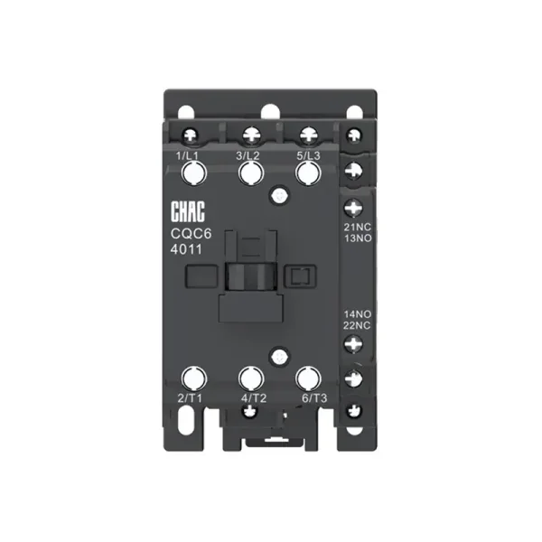
For an OEM or replacement program, approve a complete record rather than a shorthand cross-reference. A buyer evaluating an Substituição do contactor do AC should confirm ratings for the intended voltage and duty, coil characteristics, accessories, mounting, terminal capacity, ambient limits, and required documentation. Track revisions across repeat orders so a coil or auxiliary-contact change is reviewed before it reaches the assembly line. A CHAC product-family page is a starting point for documentation, not evidence of interchangeability with an installed HVAC part.
Which Standards and Safety Rules Shape the Selection?
IEC 60947-4-1 covers electromechanical contactors and motor-starters within low-voltage switchgear and controlgear. It provides performance and verification requirements. A utilization-category designation does not itself prove third-party certification or compliance of the complete HVAC assembly.
UL 60947-4-1 addresses contactors and motor-starters with North American requirements. US installation requirements must be checked against the locally adopted electrical code, equipment instructions, and any authority having jurisdiction. An IEC rating should not be presented as an automatic substitute for the documentation required for a North American assembly.
Workplace safety is a separate obligation. Under OSHA 1910.333(b)(2), control devices and interlocks cannot be the sole means of deenergizing equipment. A thermostat set to OFF or an open contactor does not establish isolation. The qualified person must address all electrical energy sources, stored energy, lockout/tagging requirements, and verification of the deenergized condition, including possible backfeed. These are US occupational requirements; other jurisdictions have their own applicable rules.
What Are the Most Common HVAC Contactor FAQs?
What does an HVAC contactor do?
It lets a low-power control signal switch a higher-power compressor, fan, pump, or heater circuit. In a conventional electromagnetic design, the coil moves the mechanism while the main contacts carry the load current. Switching does not replace overload or short-circuit protection.
How can a technician tell whether the contactor is bad?
The qualified technician confirms the control command and coil behavior during pull-in and holding, evaluates closure and release, and checks the power delivered through the contacts. An open coil, welded contacts, or abnormal contact performance may support replacement, but control-supply, termination, protection, and load faults must also be evaluated.
Why does an HVAC contactor chatter?
Possible causes include coil undervoltage, excessive control-circuit drop, poor connections, obstructed magnetic faces, vibration, or an incorrect coil frequency. Noise alone does not identify the cause. The exact coil’s operating limits and the conditions during the event matter more than a normal reading taken at another time.
Can only the contacts be replaced?
Only when the manufacturer authorizes renewal for that design and provides the correct parts and procedure. Damage to the frame, coil, terminals, arc-control parts, or mechanism may require complete replacement. The circuit condition that caused the wear still needs investigation.
Does a replacement contactor only need the same amp rating?
No. The required coil voltage and frequency, poles, compressor or motor duty, operating frequency, auxiliary contacts, terminals, mounting, environment, and market documentation all matter. A higher resistive-current rating or similar physical size does not establish replacement suitability.
Can a contactor read the correct voltage but still fail to pull in?
Yes. An unloaded or holding-state reading may miss a brief control-voltage dip during pull-in, and a mechanical obstruction can prevent closure even with an adequate supply. Distinguishing those conditions requires model-specific data and qualified diagnosis, not homeowner testing inside an energized compartment.
Is it safe to push the contactor in manually to test the compressor?
No. Manual forcing can bypass the normal control and safety sequence and expose someone to energized parts or unexpected equipment operation. Leave internal testing to a qualified technician using the equipment instructions and applicable safe-work requirements; thermostat OFF is not verified electrical isolation.
Which Sources Support These Selection and Safety Principles?
- Comissão Eletrotécnica Internacional, IEC 60947-4-1, product-standard scope and utilization categories.
- Normas e Engajamento da UL, UL 60947-4-1, North American contactor and motor-starter requirements.
- Schneider Electric, Funções de proteção do motor, updated August 5, 2026; general motor-protection guidance, not an HVAC model specification.
- Occupational Safety and Health Administration, 1910.333 Seleção e utilização de práticas de trabalho, US occupational electrical work requirements.
The replacement decision should start with the event and circuit requirements, not the appearance of the old part. First establish whether the command and control supply remain valid during pull-in; then evaluate the contact path, terminations, protection, and load. Select the replacement against the equipment’s required duty and exact coil data, and confirm the installation and documentation requirements before returning it to service. Repeated failure calls for finding the repeated stress, not simply increasing the ampere label. For a commercial HVAC or OEM application, the CHAC CQC6 Contator de HVAC product page provides a route to request model documentation and discuss the load, control, switching, and environmental requirements; it does not establish compatibility by itself.