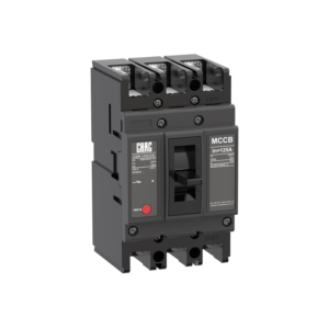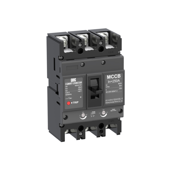
CQM6RT regolabile termicamente e magneticamente MCCB OEM
Il CQM6RT MCCB provides adjustable overload and short-circuit protection within its published 32–1250A range. Specification should follow the system voltage, load, conductor coordination, prospective fault current and applicable rules—not the ampere value alone.
Riassunto del prodotto
CQM6RT is a thermal magnetic circuit breaker for AC 400/415V distribution and protection applications. Its published range covers 32–1250A with 3P / 4P options. Selection depends on the complete power-system design, including fault level, coordination, conductor ampacity, enclosure conditions and local rules.
The supplied product specification references IEC/EN 60947-1, IEC/EN 60947-2, IEC/EN 60947-3 and IEC/EN 60947-4, together with GB/T 14048.1, .2, .3 and .4. These standard references do not, by themselves, establish certification for a particular order.
Principali caratteristiche
Applicazioni tipiche
Typical applications include industrial feeders and motor circuits where field coordination requires adjustable trip settings. These are evaluation contexts rather than universal approvals. Confirm the exact frame, voltage, breaking duty, trip unit, accessories and installation method before specification.
Modulazioni e Guida alla selezione
Use the verified CQM6RT values below to create a shortlist, then validate the complete circuit. An MCCB rating does not replace conductor calculations, fault-current analysis, coordination review or local installation requirements.
| Punto di selezione | CQM6RT reference | Cosa deve confermare il progetto |
|---|---|---|
| Corrente nominale | 32–1250A | Design current, conductor ampacity, installation method, temperature and grouping |
| Tensione | AC 400/415V | Valutazione del sistema di approvvigionamento e delle attrezzature |
| Poli | 3P / 4P | Live conductors and neutral treatment |
| Trip / protection | adjustable thermal Ir and magnetic Im | Load profile, fault response and coordination |
| Capacità di rottura | Classi C/S/M/H fino a 75kA, secondo il telaio e la configurazione ordinata | Prospective short-circuit current at the installation point |
Fixed vs Adjustable Protection
A fixed thermal-magnetic device can suit a stable design, while an adjustable trip unit may help coordination when the project study requires field settings.
Trip Coordination
Compare MCCB Options →
MCCB vs MCB
An MCCB is normally evaluated for higher current, fault duty or accessory flexibility; an MCB may be more suitable for compact final circuits.
Current & Fault Duty
Compare MCCB and MCB →
Icu vs Ics
The saved data for CQM6RT lists C/S/M/H classes up to 75kA, according to frame and ordered configuration. Match the declared duty to the prospective short-circuit current and continuity objective.
Short-Circuit Study
Review Technical Support →
Pole and Neutral Arrangement
Published pole options are 3P / 4P. Confirm which conductors must be switched, protected and isolated together.
System Arrangement
View MCCB Range →
Guida all'ordine
- State the exact model: CQM6RT.
- Provide frame and rated current within the published range: 32–1250A.
- Confirm poles: 3P / 4P.
- Specify the trip unit or protection function: adjustable thermal Ir and magnetic Im.
- Provide system voltage, frequency, application, expected fault level, destination market and quantity.
- List required accessories, terminals, documents and any approved OEM/ODM marking or packaging requirements.
Controlli di installazione e coordinamento
- Use the exact model drawing and instructions; do not infer terminal positions, supply direction or accessory compatibility from another MCCB.
- Verify conductor material and cross-section against the circuit calculation, terminal data, temperature and grouping.
- Confirm Icu/Ics or DC fault duty, upstream/downstream coordination, enclosure conditions, altitude and clearances.
- Installation, isolation, testing and maintenance must be performed by qualified personnel under applicable rules.
Selection Guide

| Product code ① | Shell frame grade ② | Shell frame grade ③ | Breaking capacity ④ | ||||
|---|---|---|---|---|---|---|---|
| CQM6 | RT | 160 | C | ||||
| Molded case circuit breaker | RT stands for thermomagnetic ally adjustable T、A stands for single adjustable (i.e.,thermally adjustable/magnetically fixed). |
C | S | M | H | ||
| 160 | 160 | 25/18 | 35/25 | 50/35 | / | ||
| 250 | 250 | 25/18 | 35/25 | 50/35 | / | ||
| 400 | 400 | / | 35/25 | 50/35 | 75/50 | ||
| 630 | 630 | / | 35/25 | 50/35 | 75/50 | ||
| 800 | 800 | / | 35/25 | 50/35 | 75/50 | ||
| 1250 | 1250 | / | 35/25 | 50/35 | 75/50 | ||
| Operating method⑤ | Number of poles⑥ | Trip Unit &Accessories⑦ | Rated current A | |
|---|---|---|---|---|
| P | 4 | 300 | 125A | |
| P:Motorized operation Z:Turn the handle W:Direct operation DElectric operation DC1 DC 2,DC3 |
160A:3P,4P 250A:3P,4P 400A:3P,4P 630A:3P,4P 800A:3P,4P 1250A:3P,4P |
The first digit indicates the type of detent 2:Instantaneous detent only 3:Duplicate detent Note:The last two digits are the accessory designator(see accessory table). |
160 | 32,40,50,63,80,100,125,140,160 |
| 250 | 100,125,140,160,180,200,225,250 | |||
| 400 | 250,315,350,400 | |||
| 630 | 250,315,350,400,500,630 | |||
| 800 | 500,630,700,800 | |||
| 1250 | 800,1000,1250 | |||
| Application⑧ | Optional code for Level 4 products⑨ | Special code⑩ |
|---|---|---|
| 2 | A | I |
| 1:For power distribution | A:N-pole unprotected,not combinable A | I:Overload alarm non trip function |
| 2:For motor protection | B:N-pole unprotected,combinable |
| Accessory Voltage ⑪ | Motorized operating voltage ⑫ | Installation ⑬ | Terminal Block Option ⑭ | |||
|---|---|---|---|---|---|---|
| Q1 | D1 | Q | 2 | |||
| Undervoltage detent UVT Q1:AC220V Q2:AC240V Q3:AC380V Q4:AC415V |
Shunt release Shunt F1:AC220V F2:AC380V F3:DC110V F4:DC24V |
Auxiliary alarm Auxiliary J1:AC125V J2:AC250V J3:DC125V J4:DC24V |
CD1 D1:AC220V D2:AC230V D3:AC380V D4:AC400V |
CD2 D5:AC230V D6:AC110V D7:DC220V D8:DC110V D9:AC110~240V D10:DC100~220V |
Q:Front of plate H:Rear of plate C:Inserted |
1:No installation 2:Installation |
| Note:When motorized operation is selected,please refer to the external accessories for the two voltages applicable for motorized operation. | ||||||
Accessory List
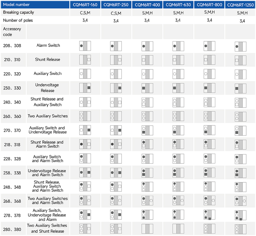
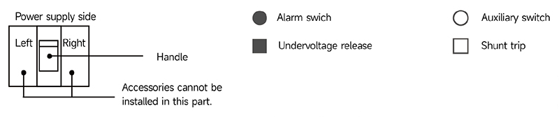
CHAC offers a right-side auxiliary switch, a left-side shunt release and a left-side undervoltage release.
For accessory codes 220, 320, 240, 340, 270 and 370, specify the required auxiliary contact arrangement when ordering.
Main Technical Parameters
| Model number | CQM6RT-160 | CQM6RT-250 | ||||||
|---|---|---|---|---|---|---|---|---|
| Rated current of frame level Inm(A) | 160 | 250 | ||||||
| Number of poles | 3,4 | 3,4 | ||||||
| Rated current In(A),at 40°C,50°C,55°C | 32,40,50,63,80,100,125,140,160 | 100,125,140,160,180,200,225,250 | ||||||
| Rated operating voltage Ue(V),AC 50/60Hz | 400/415 | 400/415 | ||||||
| Rated insulation voltage Ui (V) | 800 | 800 | ||||||
| Rated impulse withstand voltage Uimp(KV) | 8 | 8 | ||||||
| Breaking capacity designation | C | S | M | C | S | M | ||
| Short-circuit breaking capacity Icu/Ics(kA) | AC400/415V | 25/18 | 35/25 | 50/35 | 25/18 | 35/25 | 50/35 | |
| Selectivity category | A | A | A | A | A | A | ||
| Number of operating cycles ON (cycle) |
ON | 6000 | 6000 | |||||
| OFF | 10000 | 10000 | ||||||
| Trip mechanisms and protection types | Magnetic trip | Power distribution protection | ● | ● | ● | ● | ● | ● |
| Motor protection | ● | ● | ● | ● | ● | ● | ||
| Thermal-magnetic trip | Power distribution protection | ● | ● | ● | ● | ● | ● | |
| Motor protection | ● | ● | ● | ● | ● | ● | ||
| Accessory | Auxiliary contacts | ● | ● | ● | ● | ● | ● | |
| Alarm contacts | ● | ● | ● | ● | ● | ● | ||
| Shunt disconnect | ● | ● | ● | ● | ● | ● | ||
| Undervoltage detent | ● | ● | ● | ● | ● | ● | ||
| Manual operating mechanism | ● | ● | ● | ● | ● | ● | ||
| Motorized operating mechanism | ● | ● | ● | ● | ● | ● | ||
| Backplane wiring | ● | ● | ● | ● | ● | ● | ||
| Inserted | ● | ● | ● | ● | ● | ● | ||
| Coupling plate | ● | ● | ● | ● | ● | ● | ||
| Partition between phases | ● | ● | ● | ● | ● | ● | ||
| Derivative products | Dedicated for prepayment electric meters | ● | ● | ● | ● | ● | ● | |
| Overload alarm without trip | ● | ● | ● | ● | ● | ● | ||
| Overall dimensions (mm) (a-b-c-ca) | 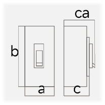 |
3 P | 90×155×71×95 | 90×155 ×85×109 | 105×165×71×96 | 105×165 ×93×119 | ||
| 4 P | 120×155×71×95 | 120×155 ×85×109 | 140×165×71×96 | 140×165 ×93×119 | ||||
Note: ● indicates an available optional accessory; – indicates that the accessory is not available.
| Model number | CQM6RT-400 | CQM6RT-630 | ||||||
|---|---|---|---|---|---|---|---|---|
| Rated current of frame level Inm(A) | 400 | 630 | ||||||
| Number of poles | 3,4 | 3,4 | ||||||
| Rated current In(A),at 40°C,50°C,55°C | 250,315,350,400 | 250,315,350,400,630 | ||||||
| Rated operating voltage Ue(V),AC 50/60Hz | 400/415 | 400/415 | ||||||
| Rated insulation voltage Ui (V) | 800 | 800 | ||||||
| Rated impulse withstand voltage Uimp(KV) | 8 | 8 | ||||||
| Breaking capacity designation | S | M | H | S | M | H | ||
| Short-circuit breaking capacity Icu/Ics(kA) | AC400/415V | 35/25 | 50/35 | 75/50 | 35/25 | 50/35 | 75/50 | |
| Selectivity category | A | A | A | A | A | A | ||
| Number of operating cycles (cycle) |
ON | 3000 | 3000 | |||||
| OFF | 8000 | 8000 | ||||||
| Trip mechanisms and protection types | Magnetic trip | Power distribution protection | ● | ● | ● | ● | ● | ● |
| Motor protection | ● | ● | ● | ● | ● | ● | ||
| Thermal-magnetic trip | Power distribution protection | ● | ● | ● | ● | ● | ● | |
| Motor protection | ● | ● | ● | ● | ● | ● | ||
| Accessory | Auxiliary contacts | ● | ● | ● | ● | ● | ● | |
| Alarm contacts | ● | ● | ● | ● | ● | ● | ||
| Shunt disconnect | ● | ● | ● | ● | ● | ● | ||
| Undervoltage detent | ● | ● | ● | ● | ● | ● | ||
| Manual operating mechanism | ● | ● | ● | ● | ● | ● | ||
| Motorized operating mechanism | ● | ● | ● | ● | ● | ● | ||
| Backplane wiring | ● | ● | ● | ● | ● | ● | ||
| Inserted | ● | ● | ● | ● | ● | ● | ||
| Coupling plate | ● | ● | ● | ● | ● | ● | ||
| Partition between phases | ● | ● | ● | ● | ● | ● | ||
| Derivative products | Dedicated for prepayment electric meters | ● | ● | ● | ● | ● | ● | |
| Overload alarm without trip | ● | ● | ● | ● | ● | ● | ||
| Overall dimensions (mm) (a-b-c-ca) | |
3 P | 140×257×108×156 | 140×257×108×156 | ||||
| 4 P | 185×257×108×156 | 185×257×108×156 | ||||||
Note: ● indicates an available optional accessory; – indicates that the accessory is not available.
| Model number | CQM6RT-800 | CQM6RT-1250 | ||||||
|---|---|---|---|---|---|---|---|---|
| Rated current of frame level Inm(A) | 800 | 1250 | ||||||
| Number of poles | 3,4 | 3,4 | ||||||
| Rated current In(A),at 40°C,50°C,55°C | 500,630,700,800 | 800,1000,1250 | ||||||
| Rated operating voltage Ue(V),AC 50/60Hz | 400/415 | 400/415 | ||||||
| Rated insulation voltage Ui (V) | 800 | 800 | ||||||
| Rated impulse withstand voltage Uimp(KV) | 8 | 8 | ||||||
| Breaking capacity designation | S | M | H | S | M | H | ||
| Short-circuit breaking capacity Icu/Ics(kA) | AC400/415V | 35/25 | 50/35 | 75/50 | 35/25 | 50/35 | 75/50 | |
| Selectivity category | A | A | A | A | A | A | ||
| Number of operating cycles (cycle) |
ON | 1000 | 1000 | |||||
| OFF | 3000 | 3000 | ||||||
| Trip mechanisms and protection types | Magnetic trip | Power distribution protection | ● | ● | ● | ● | ● | ● |
| Motor protection | ● | ● | ● | ● | ● | ● | ||
| Thermal-magnetic trip | Power distribution protection | ● | ● | ● | ● | ● | ● | |
| Motor protection | ● | ● | ● | ● | ● | ● | ||
| Accessory | Auxiliary contacts | ● | ● | ● | ● | ● | ● | |
| Alarm contacts | ● | ● | ● | ● | ● | ● | ||
| Shunt disconnect | ● | ● | ● | ● | ● | ● | ||
| Undervoltage detent | ● | ● | ● | ● | ● | ● | ||
| Manual operating mechanism | ● | ● | ● | ● | ● | ● | ||
| Motorized operating mechanism | ● | ● | ● | ● | ● | ● | ||
| Backplane wiring | ● | ● | ● | – | – | – | ||
| Inserted | ● | ● | ● | – | – | – | ||
| Coupling plate | ● | ● | ● | ● | ● | ● | ||
| Partition between phases | ● | ● | ● | ● | ● | ● | ||
| Derivative products | Dedicated for prepayment electric meters | ● | ● | ● | ● | ● | ● | |
| Overload alarm without trip | ● | ● | ● | ● | ● | ● | ||
| Overall dimensions (mm) (a-b-c-ca) | |
3 P | 210×275×114×163 | 210×275×114×163 | ||||
| 4 P | 280×275×114×163 | 280×275×114×163 | ||||||
Note: ● indicates an available optional accessory; – indicates that the accessory is not available.
Operating Characteristics
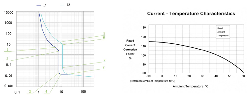
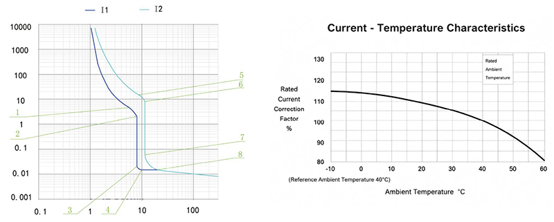
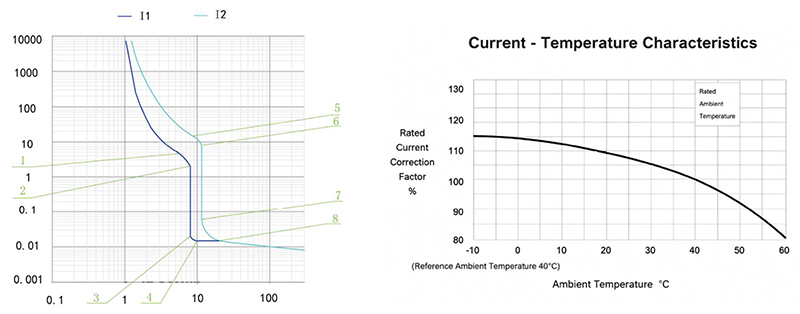
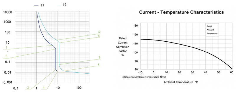
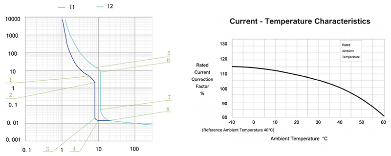
The following table gives the inverse-time operating characteristics for distribution protection with all poles energised at an ambient temperature of +40°C, without humidity compensation.
| Test current designation | Setting current multiple | Conventional time | Initial state |
|---|---|---|---|
| In≤63 In > 63 | |||
| Conventional non-tripping current | 1.05 | ≥1h ≥2h | Cool state |
| Conventional tripping current | 1.30 | <1h<2h | Hot state |
The following table gives the inverse-time operating characteristics for motor protection with all poles energised at an ambient temperature of +40°C, without humidity compensation.
| Test current designation | Setting current multiple | Conventional time | Initial state |
|---|---|---|---|
| In≤800 | |||
| Conventional non-tripping current | 1.0 | ≥2h | Cool state |
| Conventional tripping current | 1.2 | <2h | Hot state |
The operating-characteristics reference gives an instantaneous trip current setting of 10In for distribution protection. Confirm the applicable trip-unit setting for the ordered configuration.
The operating-characteristics reference gives an instantaneous trip current setting of 12In for motor protection.
The stated accuracy of the instantaneous trip current setting is 20% of the setting value.
CQM6RT-160 Operating Characteristic Curve
CQM6RT-250 Operating Characteristic Curve
CQM6RT-400 / 630 Operating Characteristic Curve
CQM6RT-800 Operating Characteristic Curve
CQM6RT-1250 Operating Characteristic Curve
Outline and Installation Dimensions(mm)
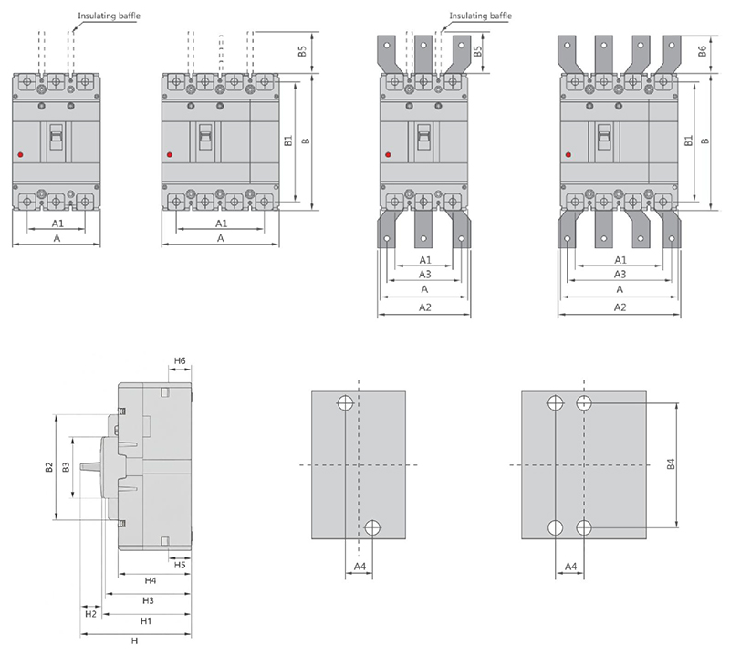
| Molded case circuit breaker | Overall dimension | Installation dimensions | Boit | |||||||||||||||||||||
|---|---|---|---|---|---|---|---|---|---|---|---|---|---|---|---|---|---|---|---|---|---|---|---|---|
| A | A1 | A2 | A3 | B | B1 | B2 | B3 | B5 | B6 | H | H1 | H2 | H3 | H4 | H5 | H6 | A4 | B4 | ||||||
| 3P | 4P | 3P | 4P | 3P | 4P | 3P | 4P | |||||||||||||||||
| CQM6RT-160CS | 90 | 120 | 60 | 90 | – | – | – | – | 155 | 134 | 103 | 50 | 48 | – | 95 | 76 | 2.2 | 70.7 | 62.3 | 23.8 | 24.6 | 30 | 132 | M8 |
| CQM6RT-160M | 90 | 120 | 60 | 90 | – | – | – | – | 155 | 134 | 103 | 50 | 48 | – | 109.2 | 90 | 2.2 | 84.9 | 76.4 | 23.1 | 24.9 | 30 | 132 | M8 |
| CQM6RT-250CS | 105 | 140 | 70 | 105 | – | – | – | – | 165 | 144 | 102 | 50 | 97 | – | 95.8 | 75 | 2.8 | 71 | 62.2 | 22.7 | 23.3 | 35 | 126 | M8 |
| CQM6RT-250M | 105 | 140 | 70 | 105 | – | – | – | – | 165 | 144 | 102 | 50 | 95 | – | 118.6 | 97.6 | 2.8 | 93.4 | 84.5 | 23.1 | 23.2 | 35 | 126 | M8 |
| CQM6RT-400 | 140 | 185 | 88 | 132 | 140 | 196 | 112 | 168 | 257 | 230 | 179 | 90 | 103 | 42 | 156 | 112.1 | 3.5 | 107.5 | 99.6 | 30.9 | 32 | 44 | 194 | M10 |
| CQM6RT-630 SMH 400A | 140 | 185 | 88 | 132 | 140 | 196 | 112 | 168 | 257 | 230 | 179 | 90 | 103 | 42 | 156 | 112.1 | 3.5 | 107.5 | 99.6 | 30.9 | 34 | 44 | 194 | M10 |
| CQM6RT-630 SMH 630A | 140 | 185 | 88 | 132 | 140 | 196 | 112 | 168 | 257 | 230 | 179 | 90 | 103 | 42 | 156 | 112.1 | 3.5 | 107.5 | 99.6 | 33.4 | 30.7 | 44 | 194 | M10 |
| CQM6RT-800 SMH 630A | 210 | 280 | 140 | 210 | 180 | 250 | 140 | 210 | 275 | 243 | 192 | 90 | 103 | 87 | 162.5 | 118.4 | 2.7 | 114.3 | 106 | 28.5 | 32.7 | 70 | 242.5 | M12 |
| CQM6RT-800 SMH 800A | 210 | 280 | 140 | 210 | 180 | 250 | 140 | 210 | 275 | 243 | 192 | 90 | 103 | 87 | 162.5 | 118.4 | 2.7 | 114.3 | 106 | 29.5 | 34.7 | 70 | 242.5 | M12 |
| CQM6RT-1250 SMH | 210 | 280 | 140 | 210 | 180 | 250 | 140 | 210 | 275 | 243 | 192 | 90 | 103 | 87 | 162.5 | 118.4 | 2.7 | 114.3 | 106 | 31.5 | 32 | 70 | 242.5 | M10 |
Perché scegliere CHAC
Con oltre 30 anni di esperienza nella produzione, oltre 1100 dipendenti e oltre 100 milioni di pali
Capacità annuale e produzione automatizzata di 90% unità, CHAC garantisce una capacità produttiva stabile e un'alta qualità dei prodotti.
Controllo qualità per clienti OEM/ODM globali. Il nostro sistema di produzione interno supporta la collaborazione a lungo termine
Cooperazione per i marchi elettrici, gli importatori e i distributori.

30+
ANNI DI ESPERIENZA
Specializzata nella produzione di apparecchiature elettriche a bassa tensione

1100+
L'EMPLOYATI
Il team professionale garantisce una qualità e una consegna stabili

100 milioni di persone
Capacità annuale delle stazioni
Capacità produttiva su larga scala per soddisfare la domanda globale

90%
PRODUZIONE AUTOMATIZZATA
Automazione avanzata per un'elevata efficienza e coerenza
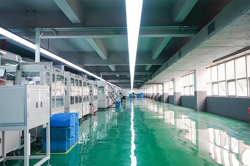
Linea di assemblaggio automatizzata

Laboratorio di test
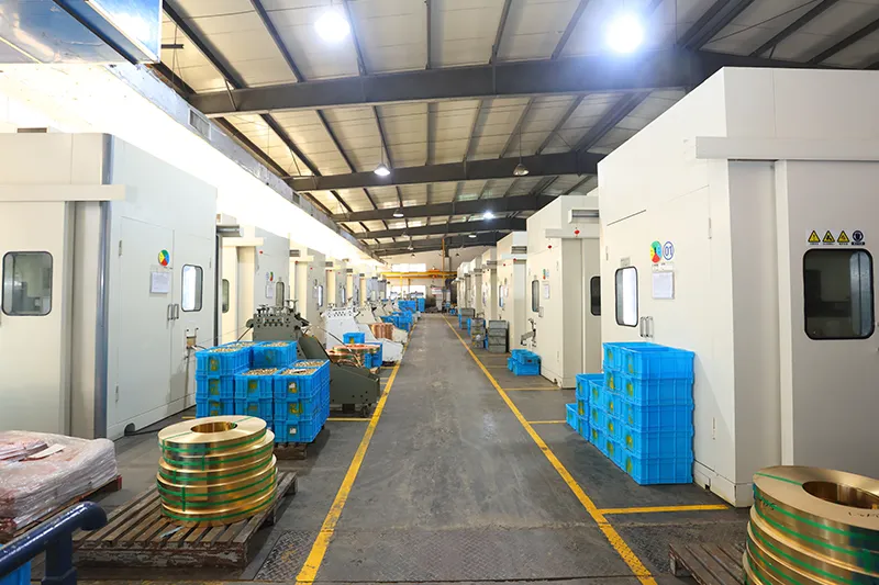
Iniezione e stampaggio
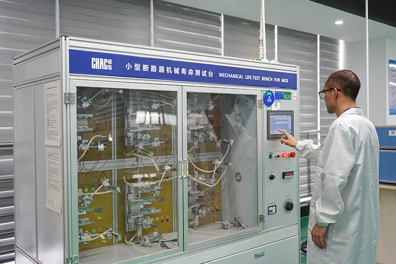
Ispezione di qualità



Un rigoroso sistema di controllo qualità assicura che ogni prodotto soddisfi gli standard internazionali.
Cosa possiamo personalizzare?
For CQM6RT projects, CHAC can review private-label marking, packaging, approved appearance options, published 32–1250A electrical configurations and technical-document requirements. Requests outside the published range are subject to engineering evaluation, testing, minimum order quantity and project feasibility.

Contenitore
Design
Dimensioni, strutture e dettagli di installazione personalizzati.
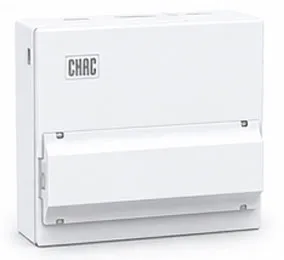

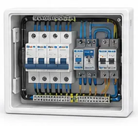
Interno
Configurazione
Opzioni di layout interno e disposizione dei componenti flessibili.

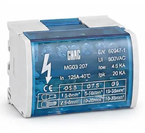
Branding &
Logo
Loghi a marchio privato, targhe e identificazione del marchio.

Imballaggio
Design
Cartoni personalizzati, etichette, manuali e soluzioni di packaging.

Elettrico
Configurazione
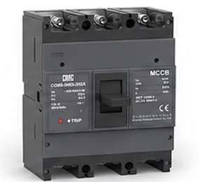
Configurazione elettrica personalizzata in base alle esigenze dell’applicazione.

Certificazione
Supporto
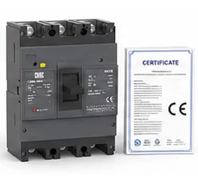
Supporto per gli standard del mercato target e per i requisiti di conformità.
Scarica
Interruttore di circuito in custodia stampata della serie CQM6
Riassunto completo dei prodotti per componenti elettrici a bassa tensione e riferimento per la scelta dei prodotti.
Necessita di documenti tecnici?
Contattateci per ricevere schede tecniche, certificati, disegni, assistenza nella scelta dei prodotti o supporto per progetti OEM/ODM.
CQM6RT Product FAQ
What is the CQM6RT MCCB used for?
The CQM6RT is specified for adjustable overload and short-circuit protection in AC 400/415V systems within the published 32–1250A range. Suitability depends on the fault study, conductor coordination, enclosure and local rules.
How does the CQM6RT molded case circuit breaker work?
The protection mechanism responds to the fault conditions stated for this model: adjustable overload and short-circuit protection. Trip behaviour, settings and interruption duty must be checked against the ordered frame and product instructions.
How do I choose the CQM6RT rated current and poles?
Start with the design current and conductor calculation, then choose a published current within 32–1250A and poles from 3P / 4P. Neutral treatment, fault level, ambient conditions and coordination also need review.
What breaking capacity should I check on the CQM6RT?
Use the declared C/S/M/H classes up to 75kA, according to frame and ordered configuration for the exact frame, voltage and configuration. The prospective short-circuit current at the installation point must be within the applicable duty; a larger ampere value alone is not a selection rule.
Can the CQM6RT replace an MCB or an earth-leakage device?
An MCCB is not automatically a like-for-like replacement. The CQM6RT provides adjustable overload and short-circuit protection; residual-current protection, DC interruption, adjustable settings and other functions must be confirmed separately from the project requirement.
How should the CQM6RT be installed and tested?
Use only the exact model drawing, terminal identification and accessory instructions. A qualified person should verify isolation, conductor size, torque, clearances, settings, fault duty and functional tests before energising the circuit.
Confirm the Right CQM6RT Configuration
Send the frame, rated current, poles, protection function, system voltage, expected fault level, destination market and quantity. CHAC will review the request against the published model range.