Un avviatore per centrale di comando motori può contenere un contattore correttamente dimensionato e tuttavia risultare un insieme non idoneo. La bobina potrebbe non essere compatibile con l’alimentazione di comando, un relè di sovraccarico potrebbe coprire un campo di corrente errato, oppure la documentazione relativa alla protezione contro i cortocircuiti potrebbe fare riferimento a un dispositivo di protezione diverso. Le dimensioni del vano possono costituire un ulteriore problema, una volta considerati gli accessori, i dispositivi di soppressione e le curvature dei cavi. Acquistare il contattore come componente isolato significa trascurare le interrelazioni che consentono al gruppo di funzionare correttamente. Questa guida illustra le informazioni da verificare, dal motore e dal servizio di esercizio fino alla combinazione completa e documentata, prima che il progetto proceda all’emissione dell’ordine.
Un Contattore MCC è un contattore selezionato per un’applicazione in un centro di controllo motori; MCC non definisce una classe di impiego universale specifica per i contattori. Iniziare dalle condizioni di alimentazione e di funzionamento del motore, dal metodo di avviamento e dal tipo di manovra. Successivamente verificare la categoria di impiego, l’alimentazione della bobina, il numero di poli, gli accessori, la disposizione delle sovraccarichi e il coordinamento con i cortocircuiti. La norma IEC 60947-4-1 fornisce il contesto pertinente per contattori e partenze, mentre i dati reali dei modelli e i documenti sulle combinazioni guidano la scelta. La compatibilità meccanica o un semplice valore di corrente nominale uguale non garantiscono l’idoneità al vano o all’intero complesso dell’MCC.
Cosa significa MCC e qual è la funzione del contattore?
MCC sta per centro di controllo motori. Indica comunemente un insieme che raggruppa unità di controllo dei motori insieme alle relative funzioni di distribuzione dell’energia e di comando. Un quadro di comando generico può servire molteplici tipi di apparecchiature; il fatto di definire un quadro come MCC non implica, di per sé, il rispetto di uno specifico standard di approvazione o di costruzione.
Il contattore assolve la funzione di commutazione specificata. Non deve essere confuso con il relè di sovraccarico, con il dispositivo di protezione dai cortocircuiti o con l’organo di sezionamento completo. Tali funzioni devono essere individuate separatamente nella progettazione del partitore, anche quando più componenti sono racchiusi in un unico alloggiamento.
Perché è necessario verificare il servizio del motore oltre alla corrente?
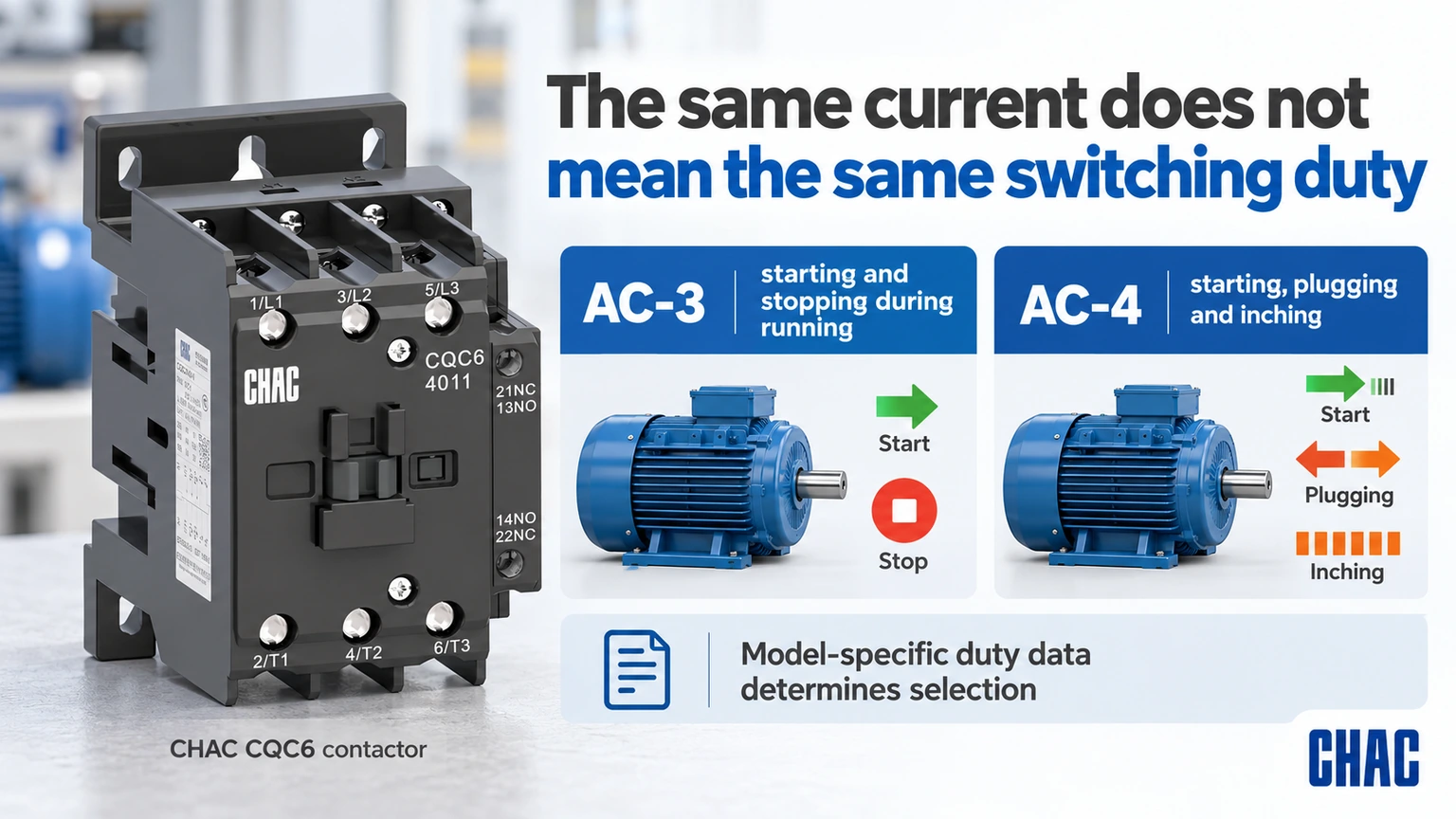
Le correnti nominali dipendono dalla tensione di esercizio e dalla categoria d’impiego. Schneider’s Guida all'utilizzo di DOCA0189EN-05 distingue l'avviamento e lo spegnimento durante il funzionamento del motore a gabbia di scoiattolo AC-3 dall'avviamento, dal freno a contracorrente e dalla marcia a scatti AC-4. Un servizio che prevede frequenti marce a scatti non può semplicemente riprendere la selezione effettuata per le normali fermate in marcia.
Includere nella specifica il numero di avviamenti orari, la sequenza di funzionamento, la durata dell’avviamento e qualsiasi configurazione a inversione di marcia o stella-triangolo. Se è presente un azionamento a frequenza variabile, attenersi alle prescrizioni del costruttore dell’azionamento per quanto riguarda eventuali contattori installati sul lato di ingresso o di uscita. Le normali ipotesi relative all’accensione diretta del motore non devono essere applicate all’uscita di un azionamento senza una verifica preliminare.
| Condizione di funzionamento | Domanda a scelta multipla | Prova richiesta |
|---|---|---|
| Avviamento e arresto normali del motore durante il funzionamento | Il modello copre l'effettivo onere AC-3? | Dati di corrente e del motore specifici per la tensione |
| Avanzamento a scatti o bloccaggio | Il gravoso compito di commutazione è coperto? | Categoria applicabile e dati di durata |
| Avviamenti frequenti | La frequenza di funzionamento e le condizioni termiche sono adeguate? | Sequenza effettiva e limiti del modello |
| Motore ad alimentazione diretta | Dove è consentito l’interscambio? | Istruzioni per il motore di trazione e il motorino di avviamento |
| Avviatore reversibile | Come si evita la chiusura simultanea? | Disposizione documentata dei controlli e degli interblocchi |
Come devono essere specificati la bobina e il circuito di controllo?
L’alimentazione di comando può differire dall’alimentazione del motore. Indicare se si tratta di corrente alternata o continua, la tensione nominale, la frequenza ove pertinente e l’esatta variante della bobina. Verificare la capacità dell’alimentazione e la caduta di tensione durante l’attivazione, non limitandosi a considerare solo la tensione a vuoto del trasformatore. Un accessorio di soppressione deve essere compatibile con la bobina effettiva e con il comportamento di comando richiesto.
Elencare i contatti ausiliari normalmente aperti (NO) e normalmente chiusi (NC) richiesti e le loro funzioni. Un ingresso del PLC, un interblocco e la bobina di un altro contattore presentano requisiti di carico di comando diversi. Il valore della corrente termica dei contatti ausiliari non sostituisce la relativa capacità di commutazione in servizio. Tenere separate le specifiche dei contatti di potenza e di quelle dei contatti di comando, affinché la distinta materiali rimanga chiara e priva di ambiguità.
In che modo si differenziano la protezione da sovraccarico e la protezione da cortocircuito?
An overload relay addresses the motor-overload duty within its specification; short-circuit protection addresses a different fault condition. The contactor’s switching rating alone does not provide either complete function. Verify the overload range, trip behavior and permitted combination with the motor and starter.
Di Schneider FA105974 coordination guidance, modified April 20, 2026, distinguishes Type 1 from Type 2 response after a short circuit. Type 1 may involve repair or replacement before service. Type 2 addresses further use under the stated conditions but still recognizes possible contact welding and required maintenance measures. The label must refer to an applicable documented combination and fault condition, not a generic promise about the contactor.
| Starter item | Cosa confermare | What is insufficient |
|---|---|---|
| Contattore | Voltage, category, current and operating duty | Frame size alone |
| Coil and auxiliaries | Control supply, logic and contact ratings | Main-circuit voltage alone |
| Overload device | Motor range and permitted settings | Similar physical width |
| Short-circuit device | Exact type, rating and combination conditions | A different breaker with the same current |
| MCC assembly | Relevant assembly rating and installation conditions | Individual component compliance alone |
What can be missed in a compartment fit check?
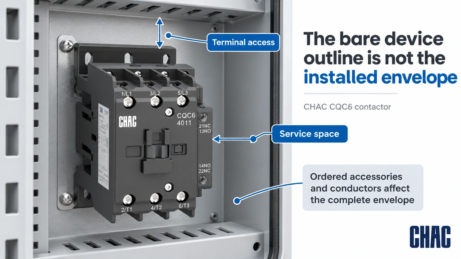
The bare contactor outline is not the complete installed envelope. Auxiliaries, interlocks, coil suppression, overload assemblies, terminals and conductor bends can extend beyond it. Check maintenance access and the mounting arrangement with all ordered accessories shown, rather than leaving the panel builder to improvise after delivery.
Ambient temperature, enclosure ventilation and adjacent heat sources also affect the review. Use the actual model instructions and assembly design limits. A component certification does not prove that any densely packed compartment will meet its thermal or short-circuit requirements.
What should happen when just one starter component is substituted?
Mark the substituted item against the approved bill of materials and identify the evidence it affects. A different short-circuit protective device can require another coordination review; a different overload range can require another motor-setting review; a different coil option can change control requirements. “Same current” is not a sufficient substitute specification for any of those decisions.
Ask for the applicable documents to identify the actual supplied combination, operating voltage, fault conditions and any required settings. Keep an accepted alternative as a separate documented configuration rather than mixing parts from several alternatives on one drawing. Where the exact combination has not been established, keep its coordination status unresolved. This preserves traceability for a future repair instead of turning a one-off procurement change into an undocumented new starter design.
Which documents should be approved before the order is released?
Prepare a motor schedule, power and control drawings, complete bill of materials, dimensioned assembly layout and the relevant coordination documents. Identify the destination market and required assembly evidence. Where documents show alternatives, record which exact alternative is being supplied rather than approving a family name.
di CHAC CQC6 contattore CA record gives a useful model-specific example: the CQC6-40 AC-3 current is listed as 40 A at 380/400 V and 34 A at 660/690 V. This is why the same model name cannot be treated as one current rating at every voltage. The values do not establish a complete MCC starter combination.
Evaluate the CQV2 motor protection circuit breaker e Relè di sovraccarico termico CQR2 by their actual functions where the design calls for them. Compatibility, coordination and the complete assembly still require confirmation. CHAC’s model records help define a motor control center contactor request, but they should be paired with the actual motor starter coordination evidence before approval.
What restart and feedback behavior belongs in the commissioning plan?
Define what the motor is permitted to do after loss and restoration of control power, a protection trip, a stop command or a feedback mismatch. For example, if a controller retains a run request, establish from the application design whether that request may be acted on when power returns. Do not assume that restoring coil voltage is permission for the machine to restart.
Prepare the expected command, contactor and feedback states with the responsible controls and machine team, then verify them under the approved commissioning procedure. Include any relevant changes to the PLC output, suppression, auxiliary contacts or interlocks. Acceptance conditions must come from the application and manufacturer requirements, not a generic delay supplied by this article. Retain the results with the control revision. Correct main-contact current ratings and a successful first start do not establish that restart prevention, stopping or safety-related functions have been validated.
How should maintenance requirements influence the selection?
Define access, identification and the information needed for a future like-for-like review. Keep the coil code and auxiliary arrangement in the maintenance record. Schneider’s contact-maintenance FAQ FA122535 illustrates why manufacturer instructions matter: for the stated NEMA and definite-purpose product lines, it advises against filing contacts. Do not turn another product’s repair method into a universal MCC maintenance rule.
After an abnormal event, use the documented inspection and return-to-service requirements. A maintenance team should be able to trace the installed combination and the applicable replacement criteria rather than reconstruct the starter from a photograph.
What are the common MCC contactor questions?
What does MCC mean in electrical?
MCC means motor control center. It generally refers to an assembly grouping motor-control units with associated power and control functions.
Is MCC the same as control panel?
Not every control panel is an MCC. An MCC has a motor-control and distribution context, while a control panel can serve many functions; the actual assembly construction and approval must be checked.
What does MCC stand for?
In this article MCC stands for motor control center. The abbreviation does not identify one universal contactor type or current rating.
What does MCC stand for in electrical terms?
It stands for motor control center. Specify the complete assembly and starter requirements rather than treating the abbreviation as an approval.
What does mcc contactor do in a control circuit?
It switches the specified load when commanded by its control circuit. Overload protection, short-circuit protection, isolation and feedback must be identified separately in the design.
How is mcc contactor different from a relay?
The application label does not establish the distinction by itself. Compare the actual power-switching duty, utilization category, ratings, coil, auxiliary arrangement and required starter combination.
Referenze
- Schneider Electric DOCA0189EN-05: utilization categories for contactors; accessed October 19, 2026
- Schneider Electric FA105974: Type 1 and Type 2 short-circuit coordination; modified April 20, 2026
- Schneider Electric FA122535: contact-maintenance boundary for the stated product lines; modified May 12, 2026
Conclusione
An MCC contactor should be approved as part of a defined starter and assembly, rather than as a stand-alone ampere rating. Begin with the motor and switching duty, then match the voltage-specific power rating, coil, auxiliaries and overload arrangement. Verify the exact short-circuit combination and the complete compartment envelope before release. A component’s approval or mechanical fit does not automatically establish the MCC assembly rating, and Type 2 coordination does not remove the manufacturer’s post-fault checks. CHAC provides model-specific contactor, motor-protection and overload-relay information that can support this review. Combining those records with the project drawings and applicable coordination evidence gives procurement and maintenance teams a configuration they can identify, install and assess consistently.