Một khởi động từ thuộc trung tâm điều khiển động cơ có thể chứa một tiếp điểm phù hợp về định mức, nhưng vẫn là một cụm lắp ráp không phù hợp. Cuộn dây có thể không tương thích với nguồn điều khiển, rơle quá tải có thể không phù hợp với dải dòng điện cần bảo vệ, hoặc tài liệu về bảo vệ ngắn mạch có thể đề cập đến một thiết bị bảo vệ khác. Kích thước của ngăn tủ cũng có thể tạo ra thêm vấn đề khi đã tính đến các phụ kiện, bộ triệt tiêu nhiễu và độ cong của cáp. Việc mua riêng lẻ tiếp điểm sẽ bỏ qua các mối liên kết cần thiết để khởi động từ hoạt động đúng chức năng. Hướng dẫn này nêu rõ những thông tin cần kiểm tra, từ đặc tính của động cơ và chế độ làm việc cho đến toàn bộ tổ hợp được lập hồ sơ đầy đủ, trước khi dự án phê duyệt đơn hàng.
An Contactor MCC là một công tắc tơ được lựa chọn cho ứng dụng trung tâm điều khiển động cơ; MCC không quy định một định mức công tắc tơ phổ quát đặc biệt. Hãy bắt đầu từ dòng điện cung cấp và dòng điện hoạt động của động cơ, phương pháp khởi động và chế độ đóng cắt. Sau đó, xác minh danh mục sử dụng, nguồn cấp cuộn dây, số cực, phụ kiện, cách bố trí bảo vệ quá tải và khả năng phối hợp ngắn mạch. IEC 60947-4-1 cung cấp bối cảnh liên quan đến công tắc tơ và bộ khởi động, trong khi dữ liệu mô hình thực tế cùng các tài liệu tổ hợp sẽ quyết định việc lựa chọn. Việc phù hợp về mặt cơ học hoặc chỉ đơn thuần là dòng điện định mức tương thích không đủ để khẳng định tính phù hợp cho ngăn tủ hoặc toàn bộ cụm MCC.
MCC có nghĩa là gì, và công tắc tơ có chức năng gì?
MCC là viết tắt của trung tâm điều khiển động cơ. Thuật ngữ này thường dùng để chỉ một cụm thiết bị tập hợp các đơn vị điều khiển động cơ cùng với các chức năng phân phối điện và điều khiển liên quan. Một tủ điều khiển chung có thể phục vụ nhiều loại thiết bị khác nhau; việc gọi một tủ điều khiển là MCC không tự nó xác định một tiêu chuẩn phê duyệt hoặc quy cách chế tạo cụ thể nào.
Contactor thực hiện chức năng đóng cắt đã được quy định. Không nên nhầm lẫn nó với rơle quá tải, thiết bị bảo vệ ngắn mạch hoặc phương tiện cách ly hoàn chỉnh. Các chức năng này cần được xác định riêng biệt trong thiết kế bộ khởi động, ngay cả khi một số chức năng được tích hợp trong cùng một ngăn.
Tại sao cần phải kiểm tra chế độ làm việc của động cơ bên cạnh việc kiểm tra dòng điện?
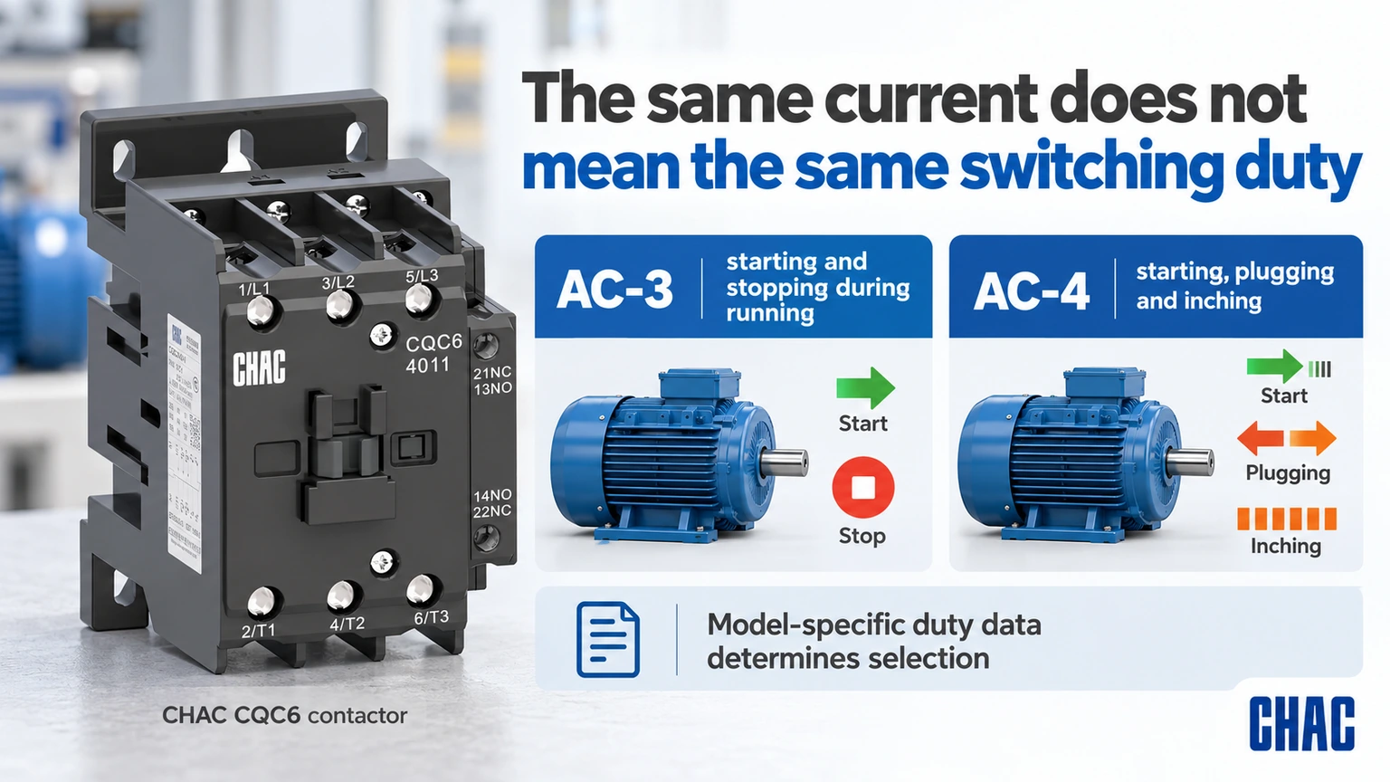
Các định mức hiện tại phụ thuộc vào điện áp vận hành và hạng mục sử dụng. Schneider’s Hướng dẫn sử dụng DOCA0189EN-05 distinguishes AC-3 squirrel-cage motor starting and switching off during running from AC-4 starting, plugging and inching. A duty involving frequent inching cannot simply inherit the selection made for ordinary running stops.
Include starts per hour, operating sequence, starting duration and any reversing or star-delta arrangement in the specification. If a variable-frequency drive is involved, follow the drive manufacturer’s rules for any contactor on its input or output. Ordinary direct-on-line motor switching assumptions should not be transferred to a drive output without review.
| Điều kiện hoạt động | Câu hỏi lựa chọn | Chứng cứ cần thiết |
|---|---|---|
| Normal motor starting and running stop | Does the model cover the actual AC-3 duty? | Voltage-specific current and motor data |
| Inching or plugging | Is the demanding switching duty covered? | Applicable category and endurance data |
| Khởi động thường xuyên | Are operating frequency and thermal conditions suitable? | Actual sequence and model limits |
| Drive-fed motor | Where is switching permitted? | Drive and starter instructions |
| Reversing starter | How is simultaneous closure prevented? | Documented control and interlock arrangement |
How should the coil and control circuit be specified?
The control supply can differ from the motor supply. State AC or DC, nominal voltage, frequency where relevant and the exact coil variant. Check the supply capacity and voltage drop during pickup, not merely the unloaded transformer output. A suppression accessory must match the actual coil and the required control behavior.
List the required NO and NC auxiliary contacts and their duties. A PLC input, an interlock and another contactor coil present different control-load requirements. An auxiliary thermal-current figure does not replace its operational switching rating. Keep the power and control contact specifications separate so the bill of materials remains unambiguous.
How do overload protection and short-circuit protection differ?
An overload relay addresses the motor-overload duty within its specification; short-circuit protection addresses a different fault condition. The contactor’s switching rating alone does not provide either complete function. Verify the overload range, trip behavior and permitted combination with the motor and starter.
Schneider’s FA105974 coordination guidance, modified April 20, 2026, distinguishes Type 1 from Type 2 response after a short circuit. Type 1 may involve repair or replacement before service. Type 2 addresses further use under the stated conditions but still recognizes possible contact welding and required maintenance measures. The label must refer to an applicable documented combination and fault condition, not a generic promise about the contactor.
| Starter item | Cần xác nhận điều gì | What is insufficient |
|---|---|---|
| Bộ phận tiếp nhận | Voltage, category, current and operating duty | Frame size alone |
| Coil and auxiliaries | Control supply, logic and contact ratings | Main-circuit voltage alone |
| Overload device | Motor range and permitted settings | Similar physical width |
| Short-circuit device | Exact type, rating and combination conditions | A different breaker with the same current |
| MCC assembly | Relevant assembly rating and installation conditions | Individual component compliance alone |
What can be missed in a compartment fit check?
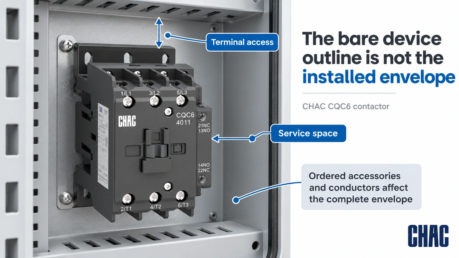
The bare contactor outline is not the complete installed envelope. Auxiliaries, interlocks, coil suppression, overload assemblies, terminals and conductor bends can extend beyond it. Check maintenance access and the mounting arrangement with all ordered accessories shown, rather than leaving the panel builder to improvise after delivery.
Ambient temperature, enclosure ventilation and adjacent heat sources also affect the review. Use the actual model instructions and assembly design limits. A component certification does not prove that any densely packed compartment will meet its thermal or short-circuit requirements.
What should happen when just one starter component is substituted?
Mark the substituted item against the approved bill of materials and identify the evidence it affects. A different short-circuit protective device can require another coordination review; a different overload range can require another motor-setting review; a different coil option can change control requirements. “Same current” is not a sufficient substitute specification for any of those decisions.
Ask for the applicable documents to identify the actual supplied combination, operating voltage, fault conditions and any required settings. Keep an accepted alternative as a separate documented configuration rather than mixing parts from several alternatives on one drawing. Where the exact combination has not been established, keep its coordination status unresolved. This preserves traceability for a future repair instead of turning a one-off procurement change into an undocumented new starter design.
Which documents should be approved before the order is released?
Prepare a motor schedule, power and control drawings, complete bill of materials, dimensioned assembly layout and the relevant coordination documents. Identify the destination market and required assembly evidence. Where documents show alternatives, record which exact alternative is being supplied rather than approving a family name.
CHAC CQC6 Contactor xoay chiều record gives a useful model-specific example: the CQC6-40 AC-3 current is listed as 40 A at 380/400 V and 34 A at 660/690 V. This is why the same model name cannot be treated as one current rating at every voltage. The values do not establish a complete MCC starter combination.
Evaluate the CQV2 motor protection circuit breaker và Rơle quá tải nhiệt CQR2 by their actual functions where the design calls for them. Compatibility, coordination and the complete assembly still require confirmation. CHAC’s model records help define a motor control center contactor request, but they should be paired with the actual phối hợp khởi động động cơ evidence before approval.
What restart and feedback behavior belongs in the commissioning plan?
Define what the motor is permitted to do after loss and restoration of control power, a protection trip, a stop command or a feedback mismatch. For example, if a controller retains a run request, establish from the application design whether that request may be acted on when power returns. Do not assume that restoring coil voltage is permission for the machine to restart.
Prepare the expected command, contactor and feedback states with the responsible controls and machine team, then verify them under the approved commissioning procedure. Include any relevant changes to the PLC output, suppression, auxiliary contacts or interlocks. Acceptance conditions must come from the application and manufacturer requirements, not a generic delay supplied by this article. Retain the results with the control revision. Correct main-contact current ratings and a successful first start do not establish that restart prevention, stopping or safety-related functions have been validated.
How should maintenance requirements influence the selection?
Define access, identification and the information needed for a future like-for-like review. Keep the coil code and auxiliary arrangement in the maintenance record. Schneider’s contact-maintenance FAQ FA122535 illustrates why manufacturer instructions matter: for the stated NEMA and definite-purpose product lines, it advises against filing contacts. Do not turn another product’s repair method into a universal MCC maintenance rule.
After an abnormal event, use the documented inspection and return-to-service requirements. A maintenance team should be able to trace the installed combination and the applicable replacement criteria rather than reconstruct the starter from a photograph.
What are the common MCC contactor questions?
What does MCC mean in electrical?
MCC means motor control center. It generally refers to an assembly grouping motor-control units with associated power and control functions.
Is MCC the same as control panel?
Not every control panel is an MCC. An MCC has a motor-control and distribution context, while a control panel can serve many functions; the actual assembly construction and approval must be checked.
What does MCC stand for?
In this article MCC stands for motor control center. The abbreviation does not identify one universal contactor type or current rating.
What does MCC stand for in electrical terms?
It stands for motor control center. Specify the complete assembly and starter requirements rather than treating the abbreviation as an approval.
What does mcc contactor do in a control circuit?
It switches the specified load when commanded by its control circuit. Overload protection, short-circuit protection, isolation and feedback must be identified separately in the design.
How is mcc contactor different from a relay?
The application label does not establish the distinction by itself. Compare the actual power-switching duty, utilization category, ratings, coil, auxiliary arrangement and required starter combination.
Tham khảo
- Schneider Electric DOCA0189EN-05: utilization categories for contactors; accessed October 19, 2026
- Schneider Electric FA105974: Type 1 and Type 2 short-circuit coordination; modified April 20, 2026
- Schneider Electric FA122535: contact-maintenance boundary for the stated product lines; modified May 12, 2026
Kết luận
An MCC contactor should be approved as part of a defined starter and assembly, rather than as a stand-alone ampere rating. Begin with the motor and switching duty, then match the voltage-specific power rating, coil, auxiliaries and overload arrangement. Verify the exact short-circuit combination and the complete compartment envelope before release. A component’s approval or mechanical fit does not automatically establish the MCC assembly rating, and Type 2 coordination does not remove the manufacturer’s post-fault checks. CHAC provides model-specific contactor, motor-protection and overload-relay information that can support this review. Combining those records with the project drawings and applicable coordination evidence gives procurement and maintenance teams a configuration they can identify, install and assess consistently.