Um comando de partida em centro de controle de motores pode conter um contato‑remanete de especificação adequada e, ainda assim, constituir uma montagem inadequada. A bobina pode não corresponder à fonte de alimentação de comando, um relé de sobrecarga pode abranger a faixa de corrente errada, ou a documentação relativa à proteção contra curto‑circuito pode fazer referência a um dispositivo de proteção diferente. As dimensões do compartimento podem gerar outro problema quando se consideram os acessórios, os dispositivos de supressão e as curvas dos cabos. Adquirir o contato‑remanete como componente isolado ignora as interdependências que garantem o funcionamento do comando de partida. Este guia apresenta as informações que devem ser verificadas, desde as características do motor e da condição de serviço até a combinação completa e devidamente documentada, antes que o projeto autorize a emissão do pedido.
Um Contator MCC é um contatoreselcionado para uma aplicação em um centro de controle de motores; o MCC não define uma classificação especial universal para contatores. Comece pela corrente de alimentação e de operação do motor, pelo método de partida e pela tarefa de comutação. Em seguida, verifique a categoria de utilização, a alimentação da bobina, os polos, os acessórios, a configuração de sobrecarga e a coordenação contra curto-circuito. A IEC 60947-4-1 fornece o contexto relevante para contatores e partidas, enquanto os dados reais do modelo e os documentos de combinação controlam a seleção. O encaixe mecânico ou apenas um valor de amperagem correspondente não garantem a adequação ao compartimento ou à montagem completa do MCC.
O que significa MCC e qual é a função do contatores?
MCC significa centro de controle de motores. Geralmente, refere-se a um conjunto que agrupa unidades de controle de motores juntamente com as respectivas funções de distribuição de energia e de controle. Um painel de controle geral pode atender a diversos tipos de equipamentos; denominar um painel como MCC, por si só, não estabelece uma aprovação específica do conjunto nem um padrão de construção.
O contator executa a função de comutação especificada. Ele não deve ser confundido com o relé de sobrecarga, com o dispositivo de proteção contra curto-circuito ou com o dispositivo de isolamento completo. Essas funções devem ser definidas separadamente no projeto do comando, mesmo quando várias delas estiverem integradas em um único compartimento.
Por que o regime de funcionamento do motor deve ser verificado, além da corrente?
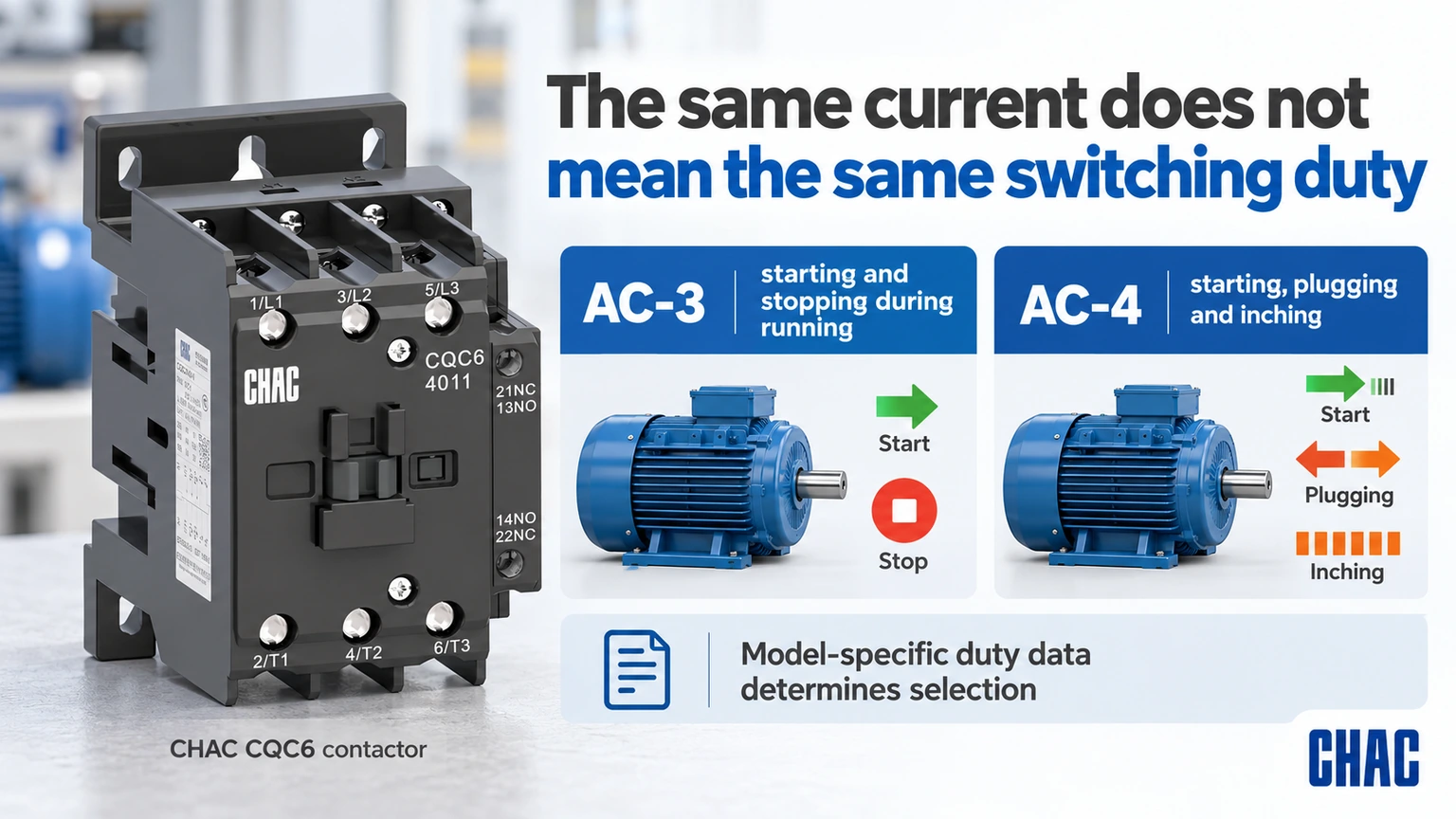
As classificações atuais dependem da tensão de operação e da categoria de utilização. Schneider’s Guia de utilização de DOCA0189EN-05 distingue a partida e o desligamento durante o funcionamento do motor de gaiola de esquilo AC-3 da partida, frenagem por inversão de fase e avanço em passo a passo AC-4. Uma tarefa que envolve avanço em passo a passo frequente não pode simplesmente herdar a seleção feita para paradas normais durante o funcionamento.
Inclua na especificação o número de partidas por hora, a sequência de operação, a duração das partidas e qualquer configuração de reversão ou estrela-triângulo. Caso seja utilizado um inversor de frequência, siga as recomendações do fabricante do inversor quanto aos contatos dos contatores instalados em sua entrada ou saída. As premissas usuais de comutação direta de motores não devem ser aplicadas à saída de um inversor sem uma análise prévia.
| Condições de operação | Pergunta de seleção | Evidência necessária |
|---|---|---|
| Partida e parada normais do motor em funcionamento | O modelo cobre a obrigação real de AC-3? | Dados de corrente e motor específicos da tensão |
| Avanço gradual ou entupimento | O exigente dever de comutação está coberto? | Categoria aplicável e dados de resistência |
| Iniciativas frequentes | A frequência de operação e as condições térmicas são adequadas? | Sequência atual e limites do modelo |
| Motor alimentado por acionamento | Onde a troca é permitida? | Instruções do acionador e do motor de partida |
| Partida reversora | Como a interrupção simultânea é evitada? | Arranjo documentado de controle e intertravamento |
How should the coil and control circuit be specified?
The control supply can differ from the motor supply. State AC or DC, nominal voltage, frequency where relevant and the exact coil variant. Check the supply capacity and voltage drop during pickup, not merely the unloaded transformer output. A suppression accessory must match the actual coil and the required control behavior.
List the required NO and NC auxiliary contacts and their duties. A PLC input, an interlock and another contactor coil present different control-load requirements. An auxiliary thermal-current figure does not replace its operational switching rating. Keep the power and control contact specifications separate so the bill of materials remains unambiguous.
How do overload protection and short-circuit protection differ?
An overload relay addresses the motor-overload duty within its specification; short-circuit protection addresses a different fault condition. The contactor’s switching rating alone does not provide either complete function. Verify the overload range, trip behavior and permitted combination with the motor and starter.
Schneider’s FA105974 coordination guidance, modified April 20, 2026, distinguishes Type 1 from Type 2 response after a short circuit. Type 1 may involve repair or replacement before service. Type 2 addresses further use under the stated conditions but still recognizes possible contact welding and required maintenance measures. The label must refer to an applicable documented combination and fault condition, not a generic promise about the contactor.
| Starter item | O que confirmar | What is insufficient |
|---|---|---|
| Contatador | Voltage, category, current and operating duty | Frame size alone |
| Coil and auxiliaries | Control supply, logic and contact ratings | Main-circuit voltage alone |
| Overload device | Motor range and permitted settings | Similar physical width |
| Short-circuit device | Exact type, rating and combination conditions | A different breaker with the same current |
| MCC assembly | Relevant assembly rating and installation conditions | Individual component compliance alone |
What can be missed in a compartment fit check?
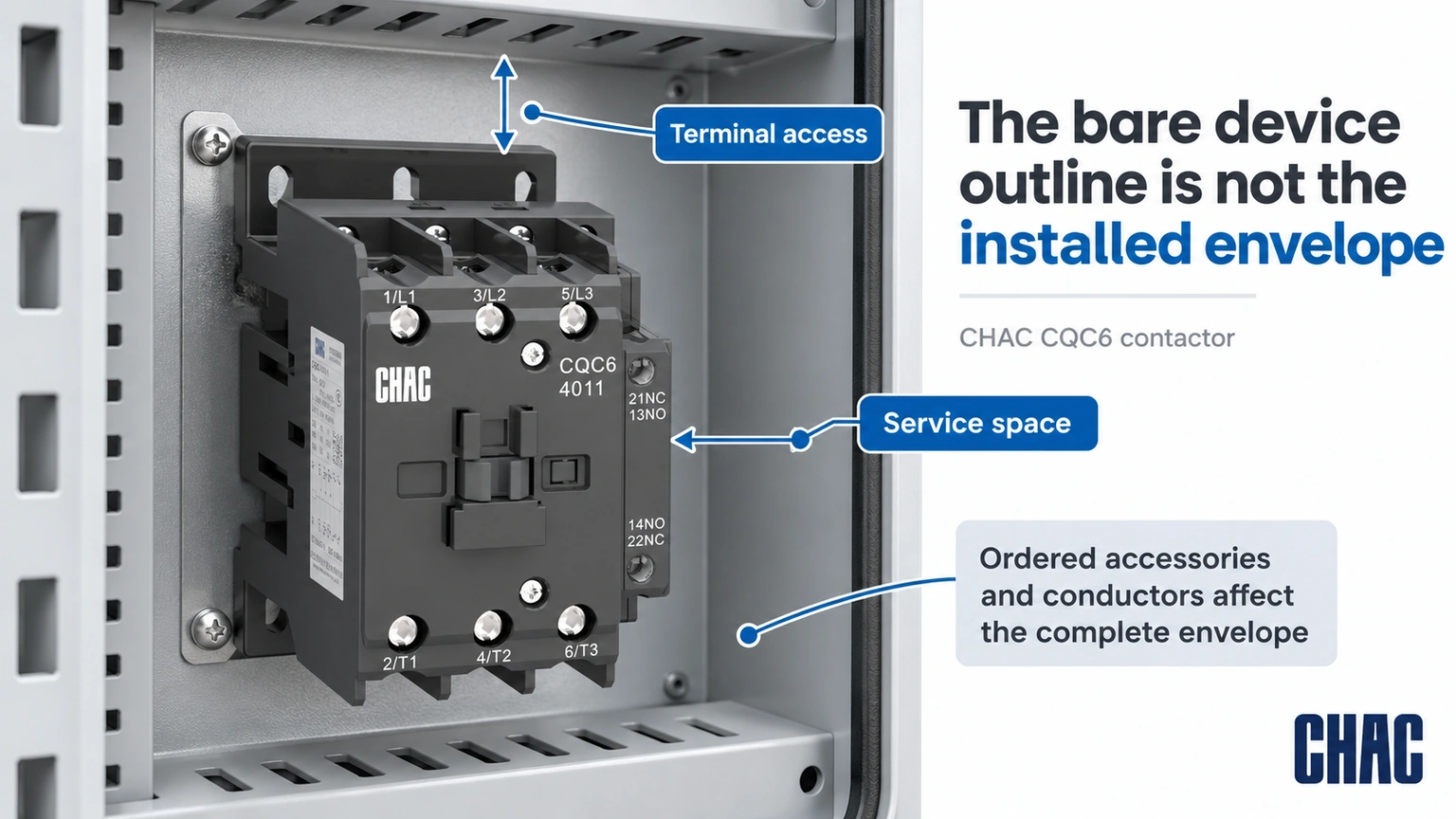
The bare contactor outline is not the complete installed envelope. Auxiliaries, interlocks, coil suppression, overload assemblies, terminals and conductor bends can extend beyond it. Check maintenance access and the mounting arrangement with all ordered accessories shown, rather than leaving the panel builder to improvise after delivery.
Ambient temperature, enclosure ventilation and adjacent heat sources also affect the review. Use the actual model instructions and assembly design limits. A component certification does not prove that any densely packed compartment will meet its thermal or short-circuit requirements.
What should happen when just one starter component is substituted?
Mark the substituted item against the approved bill of materials and identify the evidence it affects. A different short-circuit protective device can require another coordination review; a different overload range can require another motor-setting review; a different coil option can change control requirements. “Same current” is not a sufficient substitute specification for any of those decisions.
Ask for the applicable documents to identify the actual supplied combination, operating voltage, fault conditions and any required settings. Keep an accepted alternative as a separate documented configuration rather than mixing parts from several alternatives on one drawing. Where the exact combination has not been established, keep its coordination status unresolved. This preserves traceability for a future repair instead of turning a one-off procurement change into an undocumented new starter design.
Which documents should be approved before the order is released?
Prepare a motor schedule, power and control drawings, complete bill of materials, dimensioned assembly layout and the relevant coordination documents. Identify the destination market and required assembly evidence. Where documents show alternatives, record which exact alternative is being supplied rather than approving a family name.
CHAC’s Contator CA CQC6 record gives a useful model-specific example: the CQC6-40 AC-3 current is listed as 40 A at 380/400 V and 34 A at 660/690 V. This is why the same model name cannot be treated as one current rating at every voltage. The values do not establish a complete MCC starter combination.
Evaluate the Disjuntor de proteção do motor CQV2 e Relé de sobrecarga térmica CQR2 by their actual functions where the design calls for them. Compatibility, coordination and the complete assembly still require confirmation. CHAC’s model records help define a motor control center contactor request, but they should be paired with the actual Coordenação do arranque do motor evidence before approval.
What restart and feedback behavior belongs in the commissioning plan?
Define what the motor is permitted to do after loss and restoration of control power, a protection trip, a stop command or a feedback mismatch. For example, if a controller retains a run request, establish from the application design whether that request may be acted on when power returns. Do not assume that restoring coil voltage is permission for the machine to restart.
Prepare the expected command, contactor and feedback states with the responsible controls and machine team, then verify them under the approved commissioning procedure. Include any relevant changes to the PLC output, suppression, auxiliary contacts or interlocks. Acceptance conditions must come from the application and manufacturer requirements, not a generic delay supplied by this article. Retain the results with the control revision. Correct main-contact current ratings and a successful first start do not establish that restart prevention, stopping or safety-related functions have been validated.
How should maintenance requirements influence the selection?
Define access, identification and the information needed for a future like-for-like review. Keep the coil code and auxiliary arrangement in the maintenance record. Schneider’s contact-maintenance FAQ FA122535 illustrates why manufacturer instructions matter: for the stated NEMA and definite-purpose product lines, it advises against filing contacts. Do not turn another product’s repair method into a universal MCC maintenance rule.
After an abnormal event, use the documented inspection and return-to-service requirements. A maintenance team should be able to trace the installed combination and the applicable replacement criteria rather than reconstruct the starter from a photograph.
What are the common MCC contactor questions?
What does MCC mean in electrical?
MCC means motor control center. It generally refers to an assembly grouping motor-control units with associated power and control functions.
Is MCC the same as control panel?
Not every control panel is an MCC. An MCC has a motor-control and distribution context, while a control panel can serve many functions; the actual assembly construction and approval must be checked.
What does MCC stand for?
In this article MCC stands for motor control center. The abbreviation does not identify one universal contactor type or current rating.
What does MCC stand for in electrical terms?
It stands for motor control center. Specify the complete assembly and starter requirements rather than treating the abbreviation as an approval.
What does mcc contactor do in a control circuit?
It switches the specified load when commanded by its control circuit. Overload protection, short-circuit protection, isolation and feedback must be identified separately in the design.
How is mcc contactor different from a relay?
The application label does not establish the distinction by itself. Compare the actual power-switching duty, utilization category, ratings, coil, auxiliary arrangement and required starter combination.
Referências
- Schneider Electric DOCA0189EN-05: utilization categories for contactors; accessed October 19, 2026
- Schneider Electric FA105974: Type 1 and Type 2 short-circuit coordination; modified April 20, 2026
- Schneider Electric FA122535: contact-maintenance boundary for the stated product lines; modified May 12, 2026
Conclusão
An MCC contactor should be approved as part of a defined starter and assembly, rather than as a stand-alone ampere rating. Begin with the motor and switching duty, then match the voltage-specific power rating, coil, auxiliaries and overload arrangement. Verify the exact short-circuit combination and the complete compartment envelope before release. A component’s approval or mechanical fit does not automatically establish the MCC assembly rating, and Type 2 coordination does not remove the manufacturer’s post-fault checks. CHAC provides model-specific contactor, motor-protection and overload-relay information that can support this review. Combining those records with the project drawings and applicable coordination evidence gives procurement and maintenance teams a configuration they can identify, install and assess consistently.