Un démarreur de centre de commande des moteurs peut comporter un contacteur de calibre approprié tout en restant un ensemble inadapté. La bobine peut ne pas correspondre à l’alimentation de commande, un relais de surcharge peut couvrir une plage de courant incorrecte, ou la documentation relative aux courts-circuits peut faire référence à un dispositif de protection différent. Les dimensions du compartiment peuvent poser un autre problème lorsque l’on tient compte des accessoires, des dispositifs de suppression des parasites et des coudes de câbles. Acheter le contacteur comme pièce isolée revient à négliger les interactions qui assurent le bon fonctionnement du démarreur. Ce guide présente les informations à vérifier, depuis les caractéristiques du moteur et le service d’utilisation jusqu’à l’ensemble documenté complet, avant que le projet n’émette la commande.
Un Contacteur MCC est un contacteur sélectionné pour une application dans un centre de commande de moteurs ; le terme MCC ne définit pas une catégorie spéciale de contacteurs universels. Commencez par les données d’alimentation et de fonctionnement du moteur, la méthode de démarrage et la tâche de commutation. Ensuite, vérifiez la catégorie d’utilisation, l’alimentation de la bobine, le nombre de pôles, les accessoires, la disposition des protections contre les surcharges et la coordination en cas de court-circuit. La norme IEC 60947-4-1 fournit le contexte pertinent concernant les contacteurs et les démarreurs, tandis que les données réelles du modèle et les documents de combinaison régissent la sélection. Un ajustement mécanique ou un simple calibrage en ampères ne suffit pas à garantir l’adéquation au compartiment ou à l’ensemble complet du MCC.
Que signifie MCC, et quelle est la fonction du contacteur ?
MCC signifie « centre de commande des moteurs ». Il désigne généralement un ensemble regroupant des unités de commande de moteurs ainsi que les fonctions de distribution et de contrôle de puissance qui leur sont associées. Un tableau de commande général peut alimenter de nombreux types d’équipements ; le fait de qualifier un tableau de MCC n’implique pas, en soi, qu’il soit conforme à une norme particulière d’homologation ou de construction.
Le contacteur assure la fonction de commutation spécifiée. Il ne doit pas être confondu avec le relais de surcharge, l’appareil de protection contre les courts-circuits ou un dispositif d’isolement complet. Ces fonctions doivent être définies séparément dans la conception du démarreur, même lorsque plusieurs d’entre elles sont regroupées dans un même compartiment.
Pourquoi faut-il vérifier la charge du moteur en plus du courant ?
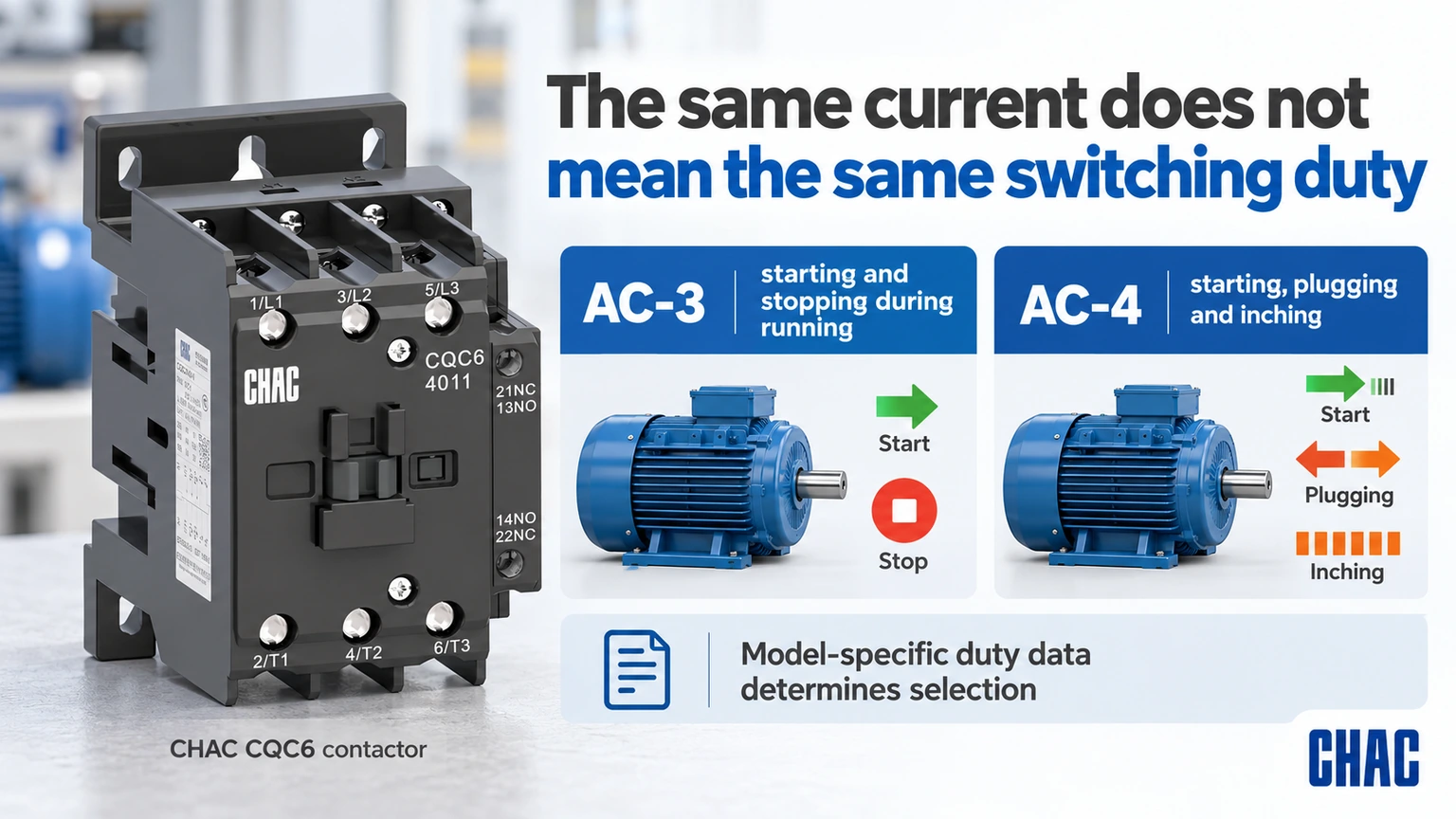
Les valeurs nominales actuelles dépendent de la tension d’exploitation et de la catégorie d’utilisation. Schneider’s Guide d'utilisation de DOCA0189EN-05 distinguishes AC-3 squirrel-cage motor starting and switching off during running from AC-4 starting, plugging and inching. A duty involving frequent inching cannot simply inherit the selection made for ordinary running stops.
Include starts per hour, operating sequence, starting duration and any reversing or star-delta arrangement in the specification. If a variable-frequency drive is involved, follow the drive manufacturer’s rules for any contactor on its input or output. Ordinary direct-on-line motor switching assumptions should not be transferred to a drive output without review.
| Conditions d'utilisation | Question de sélection | Preuve requise |
|---|---|---|
| Normal motor starting and running stop | Does the model cover the actual AC-3 duty? | Voltage-specific current and motor data |
| Inching or plugging | Is the demanding switching duty covered? | Applicable category and endurance data |
| Commences fréquemment | Are operating frequency and thermal conditions suitable? | Actual sequence and model limits |
| Drive-fed motor | Where is switching permitted? | Drive and starter instructions |
| Reversing starter | How is simultaneous closure prevented? | Documented control and interlock arrangement |
How should the coil and control circuit be specified?
The control supply can differ from the motor supply. State AC or DC, nominal voltage, frequency where relevant and the exact coil variant. Check the supply capacity and voltage drop during pickup, not merely the unloaded transformer output. A suppression accessory must match the actual coil and the required control behavior.
List the required NO and NC auxiliary contacts and their duties. A PLC input, an interlock and another contactor coil present different control-load requirements. An auxiliary thermal-current figure does not replace its operational switching rating. Keep the power and control contact specifications separate so the bill of materials remains unambiguous.
How do overload protection and short-circuit protection differ?
An overload relay addresses the motor-overload duty within its specification; short-circuit protection addresses a different fault condition. The contactor’s switching rating alone does not provide either complete function. Verify the overload range, trip behavior and permitted combination with the motor and starter.
Schneider’s FA105974 coordination guidance, modified April 20, 2026, distinguishes Type 1 from Type 2 response after a short circuit. Type 1 may involve repair or replacement before service. Type 2 addresses further use under the stated conditions but still recognizes possible contact welding and required maintenance measures. The label must refer to an applicable documented combination and fault condition, not a generic promise about the contactor.
| Starter item | Quoi confirmer | What is insufficient |
|---|---|---|
| Contrôleur | Voltage, category, current and operating duty | Frame size alone |
| Coil and auxiliaries | Control supply, logic and contact ratings | Main-circuit voltage alone |
| Overload device | Motor range and permitted settings | Similar physical width |
| Short-circuit device | Exact type, rating and combination conditions | A different breaker with the same current |
| MCC assembly | Relevant assembly rating and installation conditions | Individual component compliance alone |
What can be missed in a compartment fit check?
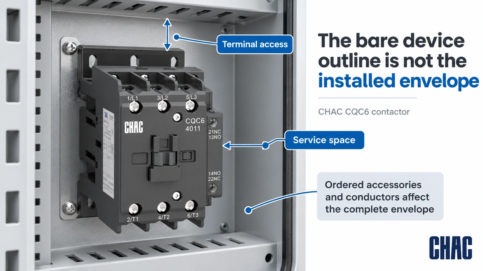
The bare contactor outline is not the complete installed envelope. Auxiliaries, interlocks, coil suppression, overload assemblies, terminals and conductor bends can extend beyond it. Check maintenance access and the mounting arrangement with all ordered accessories shown, rather than leaving the panel builder to improvise after delivery.
Ambient temperature, enclosure ventilation and adjacent heat sources also affect the review. Use the actual model instructions and assembly design limits. A component certification does not prove that any densely packed compartment will meet its thermal or short-circuit requirements.
What should happen when just one starter component is substituted?
Mark the substituted item against the approved bill of materials and identify the evidence it affects. A different short-circuit protective device can require another coordination review; a different overload range can require another motor-setting review; a different coil option can change control requirements. “Same current” is not a sufficient substitute specification for any of those decisions.
Ask for the applicable documents to identify the actual supplied combination, operating voltage, fault conditions and any required settings. Keep an accepted alternative as a separate documented configuration rather than mixing parts from several alternatives on one drawing. Where the exact combination has not been established, keep its coordination status unresolved. This preserves traceability for a future repair instead of turning a one-off procurement change into an undocumented new starter design.
Which documents should be approved before the order is released?
Prepare a motor schedule, power and control drawings, complete bill of materials, dimensioned assembly layout and the relevant coordination documents. Identify the destination market and required assembly evidence. Where documents show alternatives, record which exact alternative is being supplied rather than approving a family name.
CHAC CQC6 contacteur CA record gives a useful model-specific example: the CQC6-40 AC-3 current is listed as 40 A at 380/400 V and 34 A at 660/690 V. This is why the same model name cannot be treated as one current rating at every voltage. The values do not establish a complete MCC starter combination.
Evaluate the CQV2 disjoncteur de protection moteur et Relais de surcharge thermique CQR2 by their actual functions where the design calls for them. Compatibility, coordination and the complete assembly still require confirmation. CHAC’s model records help define a motor control center contactor request, but they should be paired with the actual motor starter coordination evidence before approval.
What restart and feedback behavior belongs in the commissioning plan?
Define what the motor is permitted to do after loss and restoration of control power, a protection trip, a stop command or a feedback mismatch. For example, if a controller retains a run request, establish from the application design whether that request may be acted on when power returns. Do not assume that restoring coil voltage is permission for the machine to restart.
Prepare the expected command, contactor and feedback states with the responsible controls and machine team, then verify them under the approved commissioning procedure. Include any relevant changes to the PLC output, suppression, auxiliary contacts or interlocks. Acceptance conditions must come from the application and manufacturer requirements, not a generic delay supplied by this article. Retain the results with the control revision. Correct main-contact current ratings and a successful first start do not establish that restart prevention, stopping or safety-related functions have been validated.
How should maintenance requirements influence the selection?
Define access, identification and the information needed for a future like-for-like review. Keep the coil code and auxiliary arrangement in the maintenance record. Schneider’s contact-maintenance FAQ FA122535 illustrates why manufacturer instructions matter: for the stated NEMA and definite-purpose product lines, it advises against filing contacts. Do not turn another product’s repair method into a universal MCC maintenance rule.
After an abnormal event, use the documented inspection and return-to-service requirements. A maintenance team should be able to trace the installed combination and the applicable replacement criteria rather than reconstruct the starter from a photograph.
What are the common MCC contactor questions?
What does MCC mean in electrical?
MCC means motor control center. It generally refers to an assembly grouping motor-control units with associated power and control functions.
Is MCC the same as control panel?
Not every control panel is an MCC. An MCC has a motor-control and distribution context, while a control panel can serve many functions; the actual assembly construction and approval must be checked.
What does MCC stand for?
In this article MCC stands for motor control center. The abbreviation does not identify one universal contactor type or current rating.
What does MCC stand for in electrical terms?
It stands for motor control center. Specify the complete assembly and starter requirements rather than treating the abbreviation as an approval.
What does mcc contactor do in a control circuit?
It switches the specified load when commanded by its control circuit. Overload protection, short-circuit protection, isolation and feedback must be identified separately in the design.
How is mcc contactor different from a relay?
The application label does not establish the distinction by itself. Compare the actual power-switching duty, utilization category, ratings, coil, auxiliary arrangement and required starter combination.
Références
- Schneider Electric DOCA0189EN-05: utilization categories for contactors; accessed October 19, 2026
- Schneider Electric FA105974: Type 1 and Type 2 short-circuit coordination; modified April 20, 2026
- Schneider Electric FA122535: contact-maintenance boundary for the stated product lines; modified May 12, 2026
Conclusion
An MCC contactor should be approved as part of a defined starter and assembly, rather than as a stand-alone ampere rating. Begin with the motor and switching duty, then match the voltage-specific power rating, coil, auxiliaries and overload arrangement. Verify the exact short-circuit combination and the complete compartment envelope before release. A component’s approval or mechanical fit does not automatically establish the MCC assembly rating, and Type 2 coordination does not remove the manufacturer’s post-fault checks. CHAC provides model-specific contactor, motor-protection and overload-relay information that can support this review. Combining those records with the project drawings and applicable coordination evidence gives procurement and maintenance teams a configuration they can identify, install and assess consistently.