A 1,500 W appliance can look suitable for a 15 A circuit because it falls below the familiar 1,800 W figure. That comparison is incomplete: at 120 V and unity power factor, it draws 12.5 A, and a continuous-load sizing calculation can produce a different result from a short-duration load calculation. Electronic drivers and motors also need current and startup data, not just a watt label. Before adding equipment, establish which voltage actually reaches the load, what else shares the circuit, how long maximum current lasts, and whether the wiring and equipment support that operating pattern.
The short answer is that 120 V × 15 A equals 1,800 VA, while 230 V × 15 A equals 3,450 VA. Those values equal watts only at unity power factor. For an entirely continuous load under the usual US 125% sizing treatment, 15 A / 1.25 gives 12 A, or 1,440 W at 120 V and unity power factor. Neither figure is a universal usable capacity. Confirm the adopted installation rules, complete equipment assembly, conductor conditions, other loads, and manufacturer instructions before deciding what the circuit can supply.

The phrase 15 amp circuit watt limit sounds like a single-number question, but amperes alone do not define power. Watts measure real power, while RMS voltage and current determine apparent power in a single-phase AC circuit. The correct answer therefore begins with actual supply voltage and then considers how the connected equipment behaves.
How does voltage change the power available on a 15 amp circuit?
For DC, use P = V × I. For single-phase AC, apparent power is S = VRMS × IRMS, expressed in volt-amperes (VA), and real power is P = S × PF, expressed in watts. Multiplying 120 V by 15 A gives 1,800 VA; multiplying 230 V by 15 A gives 3,450 VA. For a unity-power-factor load, the corresponding real-power values are 1,800 W and 3,450 W. These calculations do not override conductor ampacity, breaker instructions, load-duration rules, or the installation code adopted at the project location.
The 120 V example is relevant to a circuit actually supplying 120 V. A 230 V calculation applies only when the equipment receives that voltage and is suitable for it. Designers should not carry US branch-circuit assumptions into an IEC-based installation: protective-device ratings, wiring practices, disconnection requirements, and national regulations differ. Confirm both the supply arrangement and locally permitted circuit design rather than converting the watt figure alone.
For AC equipment with a power factor below 1.0, a load drawing 10 A at 120 V with a true power factor of 0.80 uses 960 W and 1,200 VA. The circuit and breaker still carry 10 A. This distinction matters for motors, magnetic equipment, LED drivers, and switched-mode power supplies: real watts alone do not establish the RMS current that wiring and terminals must accommodate.
| Illustrative single-phase scenario | Calculation | Result | What the result means |
|---|---|---|---|
| 120 V at 15 A | 120 × 15 | 1,800 VA | Equals 1,800 W only at unity power factor; not an all-day loading recommendation. |
| 120 V entirely continuous, unity-PF load where usual 125% sizing applies | 15 / 1.25 = 12 A; 120 × 12 | 1,440 W | Conditional planning value, subject to adopted rules and equipment conditions. |
| 230 V at 15 A | 230 × 15 | 3,450 VA | Equals 3,450 W only at unity power factor; national installation rules still control. |
| 120 V at 10 A and true PF 0.80 | 120 × 10 × 0.80 | 960 W; 1,200 VA | The circuit carries 10 A despite the lower real-power reading. |
Does a 120/240 V breaker marking mean the outlet supplies 240 V?
No. A device voltage rating is not a measurement of the connected supply. UL Solutions’ Panelboard Application Guide explains that panelboard voltage markings identify suitability for specified supply systems. Schneider Electric’s Fundamental characteristics of a circuit-breaker separately identifies rated operational voltage and rated current. Read the circuit arrangement and equipment nameplate; have a qualified person verify the supply when it is uncertain. A 120 V appliance does not become a 240 V appliance because the panel includes a higher voltage marking.
When does the 1,440 watt continuous-load figure apply?
Schneider Electric’s NEC Information of Note, within its Conductor Ampacity Tables Data Bulletin based on the 2017 NEC, quotes Section 210.20(A): branch-circuit overcurrent protection must be rated at least the noncontinuous load plus 125% of the continuous load. This historical reference explains the calculation; it does not establish the code edition or amendments governing a project in 2026. Determine continuous-load classification under the adopted rules, including whether maximum current is expected to persist for three hours or more.
For an entirely continuous load under that 125% treatment, 15 A / 1.25 = 12 A. At 120 V and unity power factor, 12 A equals 1,440 W. This is the origin of the familiar “80% rule,” because 12 A is 80% of 15 A. It is convenient shorthand, not a statement that every 15 A circuit is always limited to 12 A.
The same 2017-based bulletin quotes an exception where the assembly, including the protective devices, is listed for operation at 100% of its rating. UL’s Panelboard Application Guide also makes its continuous-loading guidance conditional on the assembly’s markings. A breaker carrying a 15 A label is not, by itself, evidence that this exception applies. Verify the complete assembly, installation conditions, manufacturer instructions, adopted edition, and authority having jurisdiction; do not infer a 100%-rated assembly from a product family name.
A mixed continuous load calculation should separate the two load portions instead of applying 80% to everything. Using the historical 125% relationship illustratively, an 8 A continuous load plus a 3 A noncontinuous load gives (8 × 1.25) + 3 = 13 A. A 10 A continuous load plus a 3 A noncontinuous load gives 15.5 A, even though its operating-current total is only 13 A. The second schedule exceeds a 15 A result under this method and calls for load reduction, circuit separation, or a coordinated redesign. Passing this arithmetic test does not complete conductor or equipment selection.
Load diversity also needs careful language. Two devices may rarely operate together, but that expectation does not automatically excuse a branch circuit from carrying a combination that can occur. Use a demand factor only when the governing calculation method permits it and the operating sequence is documented. For production equipment, documented controls that prevent simultaneous operation can be more defensible than an informal expectation that operators will stagger the loads.
What can reduce the circuit’s usable capacity?
How does voltage drop affect the load?
Longer conductors, smaller cross-sections, and higher current can increase voltage drop. Excessive resistance at a poor connection can also produce localized heating and voltage loss; it is a defect to investigate, not a condition to accept by lowering a spreadsheet watt limit. Equipment performance and any applicable voltage-drop requirements must be checked for the actual installation.
A falling voltage does not affect every load in the same way. A simple resistive heater produces less power, while a regulated electronic load may draw more current as it tries to maintain output. A qualified person can assess voltage at the utilization point during representative loading and calculate drop using the actual conductor material, length, size, and operating current. Voltage-drop assessment never replaces ampacity and termination checks.
Why can motors and electronics trip the breaker at startup?
Motors can draw substantial current while accelerating, and transformers or power supplies can create brief magnetizing or capacitor-charging inrush. A steady-state wattmeter reading can miss those events. Review manufacturer starting-current information, then compare current and duration with the protective device’s time-current characteristic and load-specific installation provisions. Choosing a larger breaker without reviewing the conductor and equipment path can remove needed protection.
Why can wattage alone understate current?
LED drivers, computer supplies, and variable-speed electronics may draw current in narrow pulses rather than as a smooth sine wave. Their true power factor includes phase displacement and waveform distortion, so dividing watts by nominal voltage can underestimate RMS current. Use manufacturer input-current data or suitable measurements of voltage, RMS current, real power, apparent power, and true power factor under representative operating conditions.
Several small electronic loads can also start together after a control signal or power restoration. Their nameplate wattages may fit comfortably below 1,800 W while coincident inrush challenges the breaker characteristic. For a lighting schedule, record driver input current and the number of units that can energize together. Dimming systems, emergency drivers, and networked controls should be included where their manufacturer data show an additional load or changed startup profile.
Do more outlets or an extension cord add capacity?
Adding outlets does not add watts. Every receptacle on one 15 A branch circuit shares its current capacity, and a duplex receptacle provides two connection points rather than two independent 15 A supplies. Outlet count is not a measurement of spare capacity. Connected loads, possible simultaneous operation, circuit rating, and applicable calculation rules determine suitability.
An extension cord or power strip introduces another component to check, not another supply. Read its own voltage, current, permitted-use, and operating-condition markings together with the appliance instructions. A lower-rated cord does not acquire a 15 A rating because it is plugged into a 15 A branch circuit. Length, conductor construction, connector condition, environment, and any reel instructions can affect suitability; the branch-circuit watt calculation alone cannot approve it. Do not select a flexible cord from a fixed-wiring ampacity table or substitute an approximate AWG-to-mm² conversion for its documented rating.
The same capacity distinction applies at the panel. An unused breaker position only indicates physical space; it does not prove spare service, feeder, bus, or fault-current capacity. Projects adding circuits should review the panel schedule and documented load calculation. These electrical panel upgrade ideas explain how spare ways and load management fit into the broader plan.
How should the circuit be checked before adding equipment?
Start with evidence from both circuit and load. Record nominal and minimum operating voltage, maximum steady current, real watts, apparent power, power factor, duty duration, and available startup-current data. Separate continuous from noncontinuous loads and identify combinations that can run together. Nameplate current and manufacturer data usually tell a more useful sizing story than marketing wattage alone.
Next, have the complete current path assessed: conductor material and size, insulation, wiring method, ambient temperature, bundling, splices, receptacles, terminal ratings, breaker type, and panel labeling. The 2017-based Schneider bulletin distinguishes conductor overcurrent protection from the treatment of flexible cords and identifies correction factors for small conductors. UL’s Panelboard Application Guide explains that equipment markings specify conductor material, sizes, and temperature ratings. No single wire-gauge association establishes suitability in every installation, and a similar metric cross-section is not automatic permission to substitute a different conductor.
The breaker must be suitable for the specific panel and circuit. Physical fit and a matching ampere number do not establish compatibility. Check voltage, poles, frequency, interrupting rating, trip characteristic, conductor range, panel label, and manufacturer instructions. UL’s guide describes panel-specific field-installed devices and limited classified replacement arrangements; those conditions must not be generalized to any breaker that fits.
| Capacity check | Evidence to collect | Decision it supports |
|---|---|---|
| Tensão do sistema | Supply arrangement, equipment nameplate, and loaded voltage | Establishes the correct VA/W calculation and reveals voltage drop. |
| Load profile | RMS current, duration, simultaneity, inrush, watts, VA, and PF | Separates sustained loading from brief starting events. |
| Complete wiring path | Conductor material and size, insulation, length, ambient, terminals, receptacles, and any cord ratings | Identifies ampacity, connection, and accessory limitations. |
| Protection and panel | Breaker type, characteristic, voltage, poles, interrupting rating, and approved panel arrangement | Prevents unsupported substitution and coordination errors. |
| Project rules | Destination market, adopted code, equipment instructions, and required conformity documents | Defines which calculation and product evidence apply. |
Installation rules and product ratings answer different questions. The adopted installation code controls the circuit design; device documentation establishes the product’s operating conditions. Schneider’s circuit-breaker guide distinguishes current rating, operational voltage, trip thresholds, and short-circuit breaking capacity. A 15 A current rating therefore does not establish a watt limit, fault-interruption capability at every voltage, or suitability for a particular panel.
Undersizing can cause nuisance trips, commissioning delays, and repeat service visits. Oversizing is not a shortcut because conductors, terminals, receptacles, and connected equipment may no longer be adequately protected. Compare measurement and circuit separation with the likely consequences of downtime, troubleshooting, and rework rather than considering only the protective-device purchase.
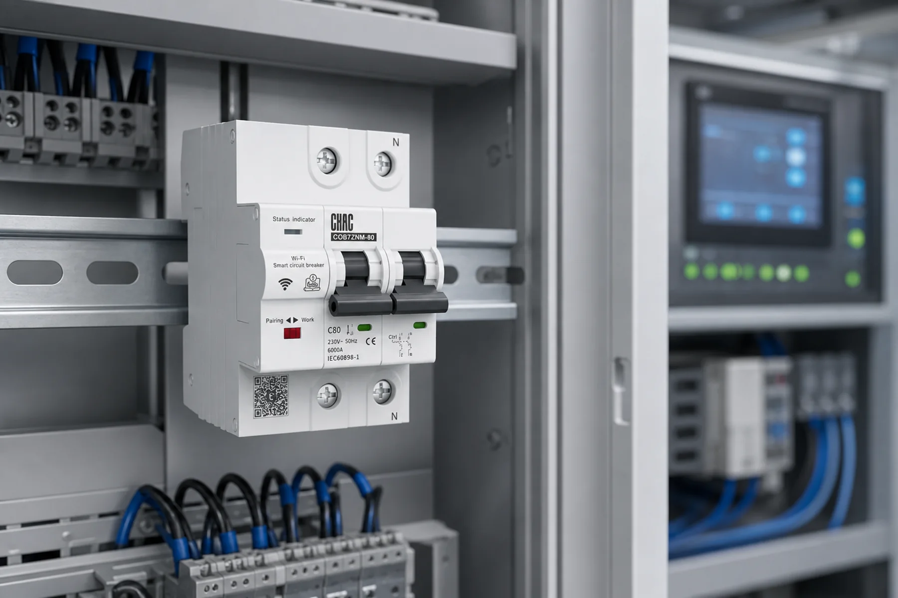
For IEC-oriented product evaluation, buyers reviewing a CHAC disjuntor miniatura should obtain exact model ratings and destination-market evidence. This general load calculation does not establish a CHAC product certification or authorize a CHAC device as a replacement in a US proprietary panel. Keep the approved datasheet revision, load schedule, panel information, measurements, and final calculation with the project record.
What else should be checked about 15 amp circuit capacity?
How many watts can a 15 amp circuit handle at 120 volts?
120 V × 15 A equals 1,800 VA, or 1,800 W at unity power factor. For an entirely continuous unity-PF load where the usual 125% sizing treatment applies, the corresponding planning value is 12 A or 1,440 W. Other loads, startup current, conductor conditions, and adopted rules still require review.
How many watts can a 15 amp circuit handle at 230 volts?
230 V × 15 A equals 3,450 VA, or 3,450 W at unity power factor. Do not automatically apply US continuous-loading assumptions to a 230 V installation. Use the actual supply voltage, equipment ratings, and national installation rules.
Can a 15 amp circuit run 1,500 watts continuously?
At 120 V and unity power factor, 1,500 W draws 12.5 A. Under the usual 125% sizing treatment, an entirely continuous 12.5 A load requires a 15.625 A result, which exceeds 15 A. Confirm the load classification and any documented assembly exception under the adopted rules rather than assuming the exception applies.
Does installing more outlets increase the available wattage?
No. Outlets on the same branch circuit share its current capacity, so more connection points do not create more power. Evaluate connected loads and simultaneous operation; a properly designed additional circuit may be needed when the existing one cannot support the requirement.
Should a tripping 15 amp breaker be replaced with a 20 amp breaker?
Not unless a qualified review confirms that the entire circuit, panel, and connected equipment are suitable for the higher rating. A trip may indicate overload, inrush, a fault, or a device problem. Use a structured circuit breaker troubleshooting process before changing the specification.
Is 15 A at 240 V equal to 3,600 W?
240 V × 15 A equals 3,600 VA and equals 3,600 W at unity power factor. That calculation requires an actual 240 V supply to suitable equipment; a panel or breaker voltage marking alone does not establish it. Pole arrangement, wiring, load duration, and applicable rules still control usability.
How many LED lights fit on a 15 A circuit?
There is no universal fixture count. Add the manufacturer’s input-current values, include other circuit loads, and evaluate operating duration, controls, and coincident inrush. Dividing a watt allowance by luminaire wattage alone can miss these constraints.
Can a 15 A extension cord carry the circuit’s full calculated wattage?
The cord’s ampere marking alone does not approve the application. Check its voltage, permitted-use and operating-condition instructions, connector ratings, appliance instructions, and any other loads on the branch circuit. The circuit calculation cannot override a lower component rating or a restriction on cord use.
Which references explain the calculation and its limits?
- NEC Information of Note, Schneider Electric, Conductor Ampacity Tables Data Bulletin based on the 2017 NEC. Historical continuous/noncontinuous sizing relationship and listed 100%-rated assembly exception; not evidence of current local adoption.
- Panelboard Application Guide, UL Solutions, accessed October 7, 2026. Panel voltage/current markings, conductor and terminal conditions, and field-installed equipment limitations.
- Fundamental characteristics of a circuit-breaker, Schneider Electric Electrical Installation Guide, last edited August 5, 2026. Rated operational voltage, current, trip settings, and breaking capacity; manufacturer examples do not establish CHAC model ratings.
The dependable answer is not a watt number by itself. Establish actual voltage and load current first, distinguish real watts from apparent power, then apply the correct duration-based calculation and verify the complete wiring and equipment path. Do not skip panel compatibility or component instructions because an arithmetic total appears acceptable. For a model-specific product review, explore CHAC Electric’s equipamento de distribuição elétrica with the load schedule, supply arrangement, destination market, and required documentation in hand.
Para uma referência de seleção relacionada, consulte How Many Watts Can a.