Imagine a hypothetical building team in London connecting a fire-alarm output to a shutdown accessory after checking only the coil label. The acceptance test finds that the intended equipment does not trip when interface power is unavailable. The fault lies in the incomplete cause-and-effect design, not simply the accessory.
Resumo: A circuit breaker fire alarm interface can mean the circuit powering the alarm or a separate alarm-controlled shutdown function. These must be designed separately. A shunt release needs its specified control energy to trip a compatible breaker; alarm continuity, interface supervision, reset behavior and acceptance testing depend on the approved fire-safety design.
Separate alarm power from alarm-controlled shutdown
O circuit breaker fire alarm topic covers two distinct circuits. One supplies the fire-alarm equipment; another may operate a shutdown interface for specified equipment. Removing power from the alarm is not a generic way to create a safe shutdown.
The fire strategy and applicable rules determine what must stop, remain available or follow a controlled sequence. Fire pumps, smoke-control equipment and other life-safety loads can have requirements that differ from ordinary building loads. Do not apply a blanket all-power-off instruction.
NFPA 72 and the locally adopted electrical and fire rules provide relevant frameworks, while the approved cause-and-effect schedule defines the project’s behavior. Commercial accessories must be assessed within that design, not treated as stand-alone approval for a fire-alarm interface.
A shunt release requires a verified control interface
A shunt-trip release operates when the specified control energy is applied, subject to its model instructions. Loss of that energy may prevent a trip. An undervoltage release has different operating behavior and should not be substituted without reviewing the intended sequence.
Check coil supply type and voltage, required operating range, energization limits and the exact compatible breaker interface. An alarm panel’s output may not be able to drive the accessory directly. Any intermediate interface, supply and supervision must be specified and approved for the complete arrangement.
Do not publish an assumed terminal-to-terminal connection for unidentified equipment. Obtain the alarm manufacturer’s approved interface requirements and the breaker accessory diagram. Identify the source of control power and the response to an open circuit, loss of power, alarm and reset.
Test the complete sequence and the return to service
An acceptance test should demonstrate the required command, actual breaker operation, feedback and reset sequence under the approved procedure. Testing only the alarm relay or only the accessory coil misses the complete chain. Coordinate tests with the responsible fire-safety and electrical personnel.
Record any permitted delay, interlock, manual reset and restart restriction. Restoring alarm status must not automatically restart equipment where that would conflict with the approved design. Label the interface and retain the current drawings for maintenance.
If there is smoke, fire or evidence of electrical damage, follow emergency procedures and leave the area when necessary. Do not open a hazardous panel, disable detection or repeatedly reset a tripping device. The interface design must support emergency response rather than creating an improvised live troubleshooting task.
Compare the selection criteria
| Circuit or device | Intended role | Important limitation |
|---|---|---|
| Alarm supply circuit | Power required detection and signaling | Do not interrupt it as generic shutdown |
| Shunt release | Trip a compatible breaker on specified energy | Control-energy availability matters |
| Undervoltage release | Operate according to supply-loss behavior | Not equivalent to a shunt release |
| Interface and feedback | Implement and confirm the approved sequence | A relay contact alone does not verify the whole chain |
Check the conditions that change the selection
| Acceptance condition | O que verificar | Record to retain |
|---|---|---|
| Alarm command | Specified equipment performs required action | Cause-and-effect test result |
| Interface supply loss | Response matches the approved design | Supply and supervision details |
| Reset and restoration | Required manual reset and restart behavior | Operating procedure |
| Maintenance change | Exact accessory and compatible breaker remain correct | Model numbers and revised diagram |
Apply the correct standards and approval scope
Apply NFPA 72 where relevant, the adopted electrical code and local fire authority requirements. A shunt accessory’s electrical rating does not establish fire-alarm listing, system supervision or approval of the overall shutdown arrangement. Project-specific interfaces require competent design and the responsible authority’s acceptance.
What to confirm before placing an order
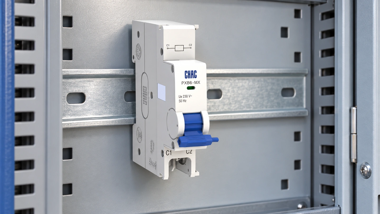
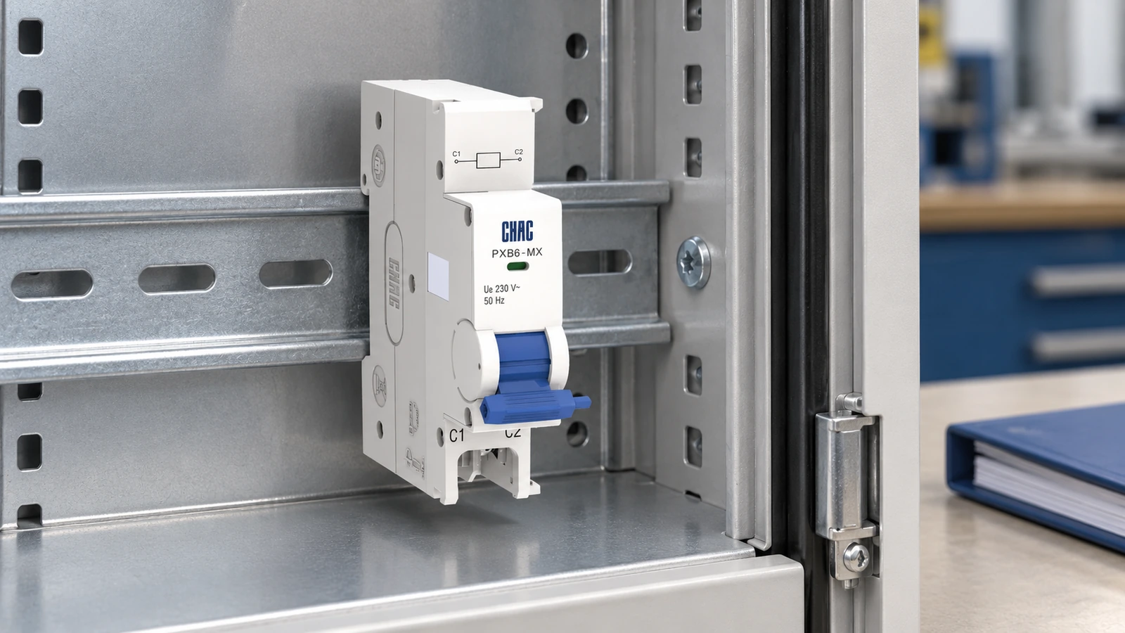
The CHAC PXB6-MX shunt release page lists an AC 230 V, 50 Hz control application and a compatible PXB6 interface; confirm the exact variant and instructions before use. Do not connect an unidentified low-voltage alarm output directly on that basis. Review breaker options e fire-alarm shutdown interfaces as a coordinated project requirement, without claiming the accessory alone is a listed fire-alarm system.
For related selection details, read the guide to ground fault versus short circuit.
Perguntas frequentes
How do I turn off the circuit breaker for my fire alarm?
Do not disable a required alarm system to silence a problem. Follow the alarm manufacturer’s procedure and involve the responsible maintenance or fire-safety personnel; use emergency services when required.
What size circuit breaker should I use for a smoke alarm?
Use the exact alarm instructions, supply requirements and locally adopted rules. Domestic smoke alarms and a building fire-alarm control panel are different equipment categories.
Why does my smoke detector trip my circuit breaker?
A circuit fault, damaged equipment or another connected load may be involved. Have a qualified person investigate; do not repeatedly reset the breaker or bypass required alarm protection.
Where is the circuit breaker for a smoke alarm?
Use verified circuit schedules and labeling, with appropriate qualified assistance if identification is uncertain. Do not disconnect circuits at random and leave detection unavailable.
What is the safest first step for a fire-alarm breaker problem?
If there is fire, smoke or immediate danger, follow evacuation and emergency procedures. Otherwise preserve required detection and arrange a qualified investigation of the alarm supply and interface.
Which extinguisher is suitable for an electrical fire?
Follow the local fire-safety plan and use an extinguisher approved for the hazard only if trained, the fire is small and an escape route remains available. Do not use water on energized equipment or delay evacuation.
Referências
- NFPA 72 — National Fire Alarm and Signaling Code
- OSHA 1910.333 — selection and use of electrical work practices
- OSHA 1910.303 — electrical equipment and installation requirements
For model-specific selection, review the CHAC product details and send the application conditions, quantity and destination requirements through the página de contacto.