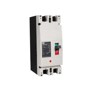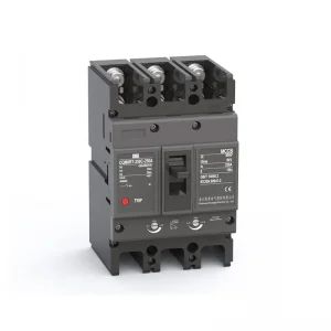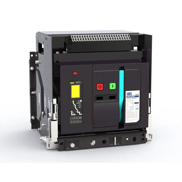
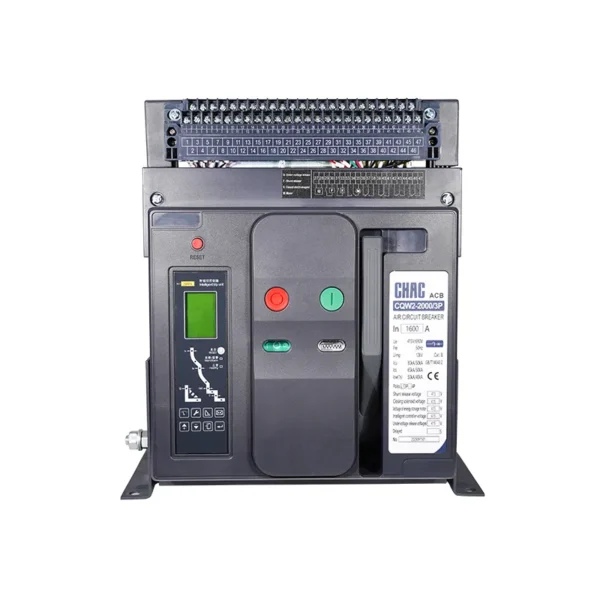
قواطع دوائر الهواء من سلسلة CQW2
ال قواطع دوائر الهواء من سلسلة CQW2 is a CHAC air circuit breaker for main low-voltage distribution protection. The page keeps the model-specific technical table and original product images so buyers can verify voltage, current, configuration, mounting and applicable standards before ordering. Final suitability depends on the complete circuit, installation method and destination-market rules.
Product Overview
CQW2 Series Air Circuit Breaker is a air circuit breaker intended for main low-voltage distribution protection. The current product record identifies it for incomers, bus couplers and large feeders. Use the exact model variant and preserved technical source as the basis for procurement rather than assuming that every family member has the same rating.
Verified source summary: Type designation Code Position Code Symbol Meaning & Explanation ① Enterprise Code Zhejiang Chuangqi Electric Co., LTD. ② Product Code Universal Circuit Breaker ③ Design Serial Number Design Serial Number ④ Frame Rating Code 1600, 2000, 3200, 4000, 6300 ⑤ Number of Poles 3: 3-Pole, 4: 4-Pole ⑥ Mounting Type D: Drawout Type, F: Fixed Type ⑦ Rated Current 200~6300A ⑧ Intelligent Controller L: Electronic Type, M: Standa
Key Features
Typical Applications
Typical use can include incomers, bus couplers and large feeders when the project confirms system voltage, current, fault or surge exposure, conductor and enclosure requirements, and the selected variant’s installation instructions. This page does not replace the project design or the authority having jurisdiction.
Applications and Selection Guide
Use the following decision points with the preserved model data. Product-family descriptions explain intent, but the exact technical table controls the ordered variant.
| Selection point | قواطع دوائر الهواء من سلسلة CQW2 | What the project must confirm |
|---|---|---|
| تطبيق | ACB projects | Confirm the actual system and environment |
| Selection basis | main low-voltage distribution protection | Use the exact model and technical table |
| Installation | Follow the model instructions | Check mounting, clearances and termination |
| Compliance | Use the listed standard where applicable | Verify edition, scope and destination rules |
| Adjacent product | Evaluate the related CHAC family where function differs | Do not substitute without engineering review |
Function
main low-voltage distribution protection
Match the protection or switching function to the system.
إعدادات
Model-specific options
Confirm current, voltage, poles, terminals or accessories from the table.
Installation
Mechanical and electrical fit
Check enclosure, mounting, wiring space and maintenance access.
Project evidence
Documents and test records
Retain the approved drawing, technical sheet and commissioning record.
Ordering Guide
- State the exact model and variant.
- Provide the system voltage, current, frequency and load or protection function.
- Confirm mounting, terminals, accessories, enclosure and environmental conditions.
- Share quantity, destination market and required technical documents.
Installation and Coordination Checks
- Verify the model’s ratings and connection arrangement against the project drawings.
- Check conductor, busbar, enclosure, clearances and tightening requirements using the product documentation.
- Coordinate upstream and downstream protection or control devices where applicable.
- Use qualified personnel for installation, testing, isolation and maintenance.
تعيين النوع

| Code Position | Code Symbol | Meaning & Explanation |
| ① | Enterprise Code | Zhejiang Chuangqi Electric Co., LTD. |
| ② | Product Code | Universal Circuit Breaker |
| ③ | Design Serial Number | Design Serial Number |
| ④ | Frame Rating Code | 1600, 2000, 3200, 4000, 6300 |
| ⑤ | Number of Poles | 3: 3-Pole, 4: 4-Pole |
| ⑥ | Mounting Type | D: Drawout Type, F: Fixed Type |
| ⑦ | Rated Current | 200~6300A |
| ⑧ | Intelligent Controller | L: Electronic Type, M: Standard Type, H: Communication Type |
| ⑨ | Control Circuit Voltage | AC230V, AC400V, DC220V, DC110V |
المواصفات الفنية
| معامل | CQW2-1600 | CQW2-2000 | CQW2-3200 | |
| Rated Current In (A) | 200, 400, 630, 800 1000, 1250, 1600 |
400, 630, 800, 1000 1250, 1600, 2000 |
2000, 2500, 2900, | |
| N-pole Rated Current | 100%In | 100%In | 100%In | |
| Rated Operational Voltage Ue | AC415V/690V | AC415V/690V | AC415V/690V | |
| Rated Frequency f | 50/60 هرتز | 50/60 هرتز | 50/60 هرتز | |
| Rated Insulation Voltage Ui | 1000V | 1250V | 1000V | |
| Rated Impulse Withstand Voltage Uimp | 12kV | 12kV | 12kV | |
| Number of Poles | 3, 4 | 3, 4 | 3, 4 | |
| Total Break Time | ≤30ms | ≤30ms | ≤30ms | |
| Closing Time | ≤70ms | ≤70ms | ≤70ms | |
| Rated Ultimate Short-Circuit | AC415V | 65kA | 80kA | 100kA |
| Breaking Capacity Icu (RMS) | AC690V | 42kA | 65kA | 75kA |
| Rated Service Short-Circuit | AC415V | 55kA | 80kA | 85kA |
| Breaking Capacity Ics (RMS) | AC690V | 35kA | 65kA | 65kA |
| Rated Making Capacity Icm | AC415V | 143kA | 176kA | 220kA |
| (Peak) | AC690V | 88kA | 143kA | 176kA |
| Rated Short-Time Withstand | AC415V | 42kA | 60kA | 85kA |
| Current Icw (RMS) | AC690V | 35kA | 40kA | 55kA |
| Operating Performance (Number of operations) |
Mechanical Life – Maintenance-Free |
10000 | 15000 | 15000 |
| Mechanical Life – With Maintenance |
10000 | 15000 | 15000 | |
| Operating Frequency | 20 operations/hour | 20 operations/hour | 20 operations/hour | |
| Electrical Life – AC415V | 15000 | 15000 | 15000 | |
| Electrical Life – AC690V | 30000 | 30000 | 30000 | |
| Operating Frequency | 60 operations/hour | 60 operations/hour | 60 operations/hour | |
| Control and Protection Unit | L Type (Electronic Type) | |||
| M Type (Standard Type) | ||||
| H Type (Communication Type) | ||||
| Connection Method | Horizontal | |||
| Vertical | ||||
| قياسي | IEC60947-2, GB/T14048.2 | |||
| معامل | CQW2-4000 | CQW2-6300 | |
| Rated Current In (A) | 3200, 3600, 4000 | 4000, 5000, 6300 | |
| N-pole Rated Current | 100%In | 100%In | |
| Rated Operational Voltage Ue | AC415V/690V | AC415V/690V | |
| Rated Frequency f | 50/60 هرتز | 50/60 هرتز | |
| Rated Insulation Voltage Ui | 1000V | 1000V | |
| Rated Impulse Withstand Voltage Uimp | 12kV | 12kV | |
| Number of Poles | 3, 4 | 3, 4 | |
| Total Break Time | ≤30ms | ≤30ms | |
| Closing Time | ≤70ms | ≤70ms | |
| Rated Ultimate Short-Circuit Breaking Capacity Icu (RMS) |
AC415V | 100kA | 120kA |
| AC690V | 80kA | 85kA | |
| Rated Service Short-Circuit Breaking Capacity Ics (RMS) |
AC415V | 85kA | 100kA |
| AC690V | 70kA | 75kA | |
| Rated Making Capacity Icm (Peak) |
AC415V | 220kA | 264kA |
| AC690V | 176kA | 187kA | |
| Rated Short-Time Withstand Current Icw (RMS) |
AC415V | 85kA | 100kA |
| AC690V | 70kA | 75kA | |
| Operating Performance (Number of operations) |
Mechanical Life – Maintenance-Free |
6000 | 1000 |
| Mechanical Life – With Maintenance |
3000 | 800 | |
| Operating Frequency | 20 operations/hour | 20 operations/hour | |
| Electrical Life – AC415V | 12500 | 5000 | |
| Electrical Life – AC690V | 25000 | 10000 | |
| Operating Frequency | 60 operations/hour | 60 operations/hour | |
| Control and Protection Unit | L Type (Electronic Type) | ||
| M Type (Standard Type) | |||
| H Type (Communication Type) | |||
| Connection Method | Horizontal | ||
| Vertical | |||
| قياسي | IEC60947-2, GB/T14048.2 | ||
Accessory List
| Accessory Name | Parameters | |
| قياسي إعدادات |
Closing Solenoid | AC230V, AC400V, DC220V, DC110V |
| Shunt Release | AC230V, AC400V, DC220V, DC110V | |
| Energy Storage Motor | AC230V, AC400V, DC220V, DC110V | |
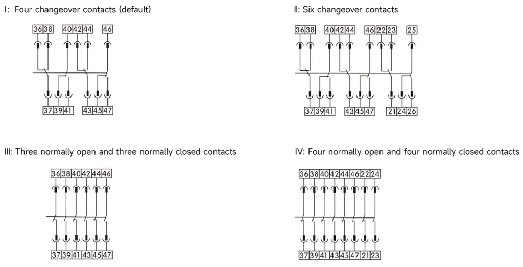
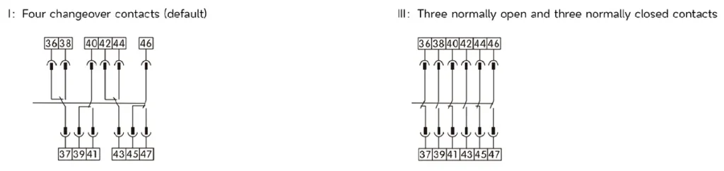
| Auxiliary Switch | 4 changeover contacts (default), 5 changeover contacts, 4NO+4NC, 6NO+6NC | |
| Others | Phase barrier, Door frame, Drawer base three-position lock | |
| Optional إعدادات |
Undervoltage Release | AC230V, AC400V |
| Instantaneous, Delayed: 0.5s, 1s, 3s, 5s | ||
| Trip Locking Device | 1 lock + 1 key, 2 locks + 1 key, 3 locks + 2 keys, 6NO+6NC | |
| Mechanical Interlock | For 2 circuit breakers: Linkage interlock (vertical), Cable interlock | |
| For 3 circuit breakers: Linkage interlock (vertical), Cable interlock | ||
| Others | Residual Current Transformer, External Neutral Current Transformer, Relay Module | |
| Communication Module (Profibus-DP), Power Module, Wireless Remote Control Module | ||
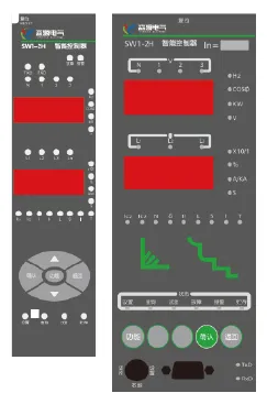
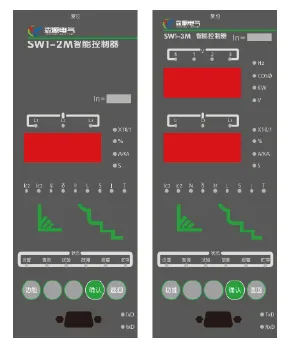
Intelligent Controller
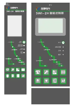
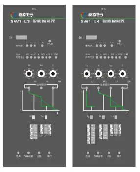
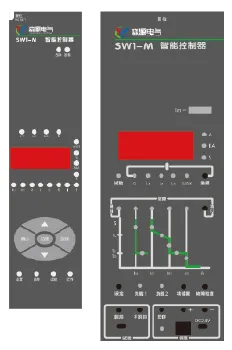
| معامل | CQW2-L | CQW2-M | CQW2-2M |
 |
 |
 |
|
| Basic Functions |
Overload long-time delay protection; Short-time delay short-circuit protection; Instantaneous short-circuit protection; Ground fault protection; Dial switch grading setting; Running current bar graph indication; Test function; Fault recording function; Thermal memory function |
Overload long-time delay protection; Short-time delay short-circuit protection; Instantaneous short-circuit protection; Ground fault protection (differential type); LED digital display; Key setting method; Ammeter function; Test function; Fault recording function; Thermal memory function |
Overload long-time delay protection; Short-time delay short-circuit protection; Instantaneous short-circuit protection; Ground fault protection (differential type); LED digital display; Key setting method; Ammeter function; Test function; Fault recording function; Thermal memory function; Clock function; Self-diagnosis function; Contact pattern and mechanical operation count |
| Optional Functions |
MCR make-break and over-limit tripping; Contact output; 3P+N type neutral protection |
MCR make-break and over-limit tripping; Contact output; Voltage function; Residual current type leakage protection; Clock function; Current unbalance protection; Remote reset function; Load monitoring function; 3P+N type neutral protection; Low voltage ride-through |
MCR make-break and over-limit tripping; Contact output; Voltage function; Residual current type leakage protection; Current unbalance protection; Remote reset function; Load monitoring function; 3P+N type neutral protection; Low voltage ride-through |
| Optional Accessories |
DC Power Module (DC110V/220V) External N-phase Transformer |
DC Power Module (DC110V/220V) External N-phase Transformer Ground Current Transformer ZT100 Residual Current Transformer ZCT1 ST201 Relay Module ST-4 Power Module ST Handheld Programmer |
DC Power Module (DC110V/220V) External N-phase Transformer Ground Current Transformer ZT100 Residual Current Transformer ZCT1 ST201 Relay Module ST-4 Power Module ST Handheld Programmer |
ملاحظة:
1.Only one of the following functions can be selected: 3P+N neutral protection, groundcurrent type leakage protection, or residual current leakage protection. The correspondingtransformer accessory must be additionally selected.
2.Only one signal unit (S1, S2, or S3) can be selected.
3.For detailed instructions on the intelligent controller, please refer to the “SW1 Series Intelligent Controller User Manual”.
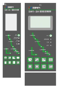
| معامل | CQW2-2H | CQW2-3M | CQW2-3H |
 |
 |
 |
|
| Basic Functions |
Overload long-time delay protection; Short-circuit short-time delay protection; Short-circuit instantaneous protection; Ground fault protection (differential type); LED digital tube display; Key setting method; Ammeter function; Fault memory function; Thermal memory function; Clock function; Self-diagnosis function; Contact pattern and mechanical operation count; Communication function |
Load monitoring (current method 1); Multi-curve long-time delay protection; Multi-curve short-time inverse-time protection; Short-time definite-time protection; Instantaneous protection; Current unbalance (phase loss) protection; Ground fault alarm; Ground fault protection (default T-type); Neutral protection; Four-phase current and ground current measurement; Thermal capacity; Eight records of faults, alarms and status changes; Historical current peak; Contact equivalent; Operation count; Clock function; Self-diagnosis; Chinese graphical LCD display; LCD status indicator; Keyboard operation |
Load monitoring (current method 1); Multi-curve long-time delay protection; Multi-curve short-time inverse-time protection; Short-time definite-time protection; Instantaneous protection; Current unbalance (phase loss) protection; Ground fault alarm; Ground fault protection (default T-type); Neutral protection; Four-phase current and ground current measurement; Thermal capacity; Eight records of faults, alarms and status changes; Historical current peak; Contact equivalent; Operation count; Clock function; Self-diagnosis; Chinese graphical LCD display; LCD status indicator; Keyboard operation; Communication function |
| Optional Functions |
MCR make-break and over-limit tripping; Contact output; Voltage function; Residual current type leakage protection; Clock function; Current unbalance protection; Remote reset function; Load monitoring function; 3P+N type neutral protection; Low voltage ride-through |
Function Table: D, U, UD, P, PD, H Select HD from the table (refer to function table description) Signal Unit: S1, S2, S3 Load Monitoring: Current Method 2 3P+N Type Neutral Protection Ground Current Type Leakage Protection Residual Current Type Leakage Protection Remote Reset Function |
Function Table: D, U, UD, P, PD, H Select HD from the table (refer to function table description) Signal Unit: S1, S2, S3 Load Monitoring: Current Method 2 3P+N Type Neutral Protection Ground Current Type Leakage Protection Residual Current Type Leakage Protection Remote Reset Function Profibus-DP Communication Protocol Device-net Communication Protocol |
| Optional Accessories |
DC Power Module (DC110V/220V) External N-phase Transformer Ground Current Transformer ZT100 Residual Current Transformer ZCT1 ST201 Relay Module ST-4 Power Module ST Handheld Programme |
DC Power Module (DC110V/220V) External N-phase Transformer Ground Current Transformer ZT100 Residual Current Transformer ZCT1 ST201 Relay Module Selective Zone Interlocking Protection Device |
DC Power Module (DC110V/220V) External N-phase Transformer Ground Current Transformer ZT100 Residual Current Transformer ZCT1 ST201 Relay Module Selective Zone Interlocking Protection Device |
| D | U | UD | P |
| Demand Measurement(Current) Demand Protection |
Voltage Measurement Frequency Measurement Voltage Unbalance Rate Measurement Phase Sequence Detection Overvoltage Protection Undervoltage Protection Voltage Unbalance Protection Overfrequency Protection Underfrequency Protection Phase Sequence Protection |
Voltage Measurement Frequency Measurement Voltage Unbalance Rate Measurement Phase Sequence Detection Current Demand Measurement Overvoltage Protection Undervoltage Protection Voltage Unbalance Protection Overfrequency Protection Underfrequency Protection Phase Sequence Protection Demand Protection |
Voltage Measurement Frequency Measurement Voltage Unbalance Rate Measurement Phase Sequence Detection Power Measurement Power Factor Measurement Energy Measurement Overvoltage Protection Undervoltage Protection Voltage Unbalance Protection Overfrequency Protection Underfrequency Protection Phase Sequence Protection |
| PD | H | HD |
| Voltage Measurement Frequency Measurement Voltage Unbalance Rate Measurement Phase Sequence Detection Power Measurement Power Factor Measurement Energy Measurement Demand Measurement (Current, Power) Overvoltage Protection Undervoltage Protection Voltage Unbalance Protection Overfrequency Protection Underfrequency Protection Phase Sequence Protection |
Voltage Measurement Frequency Measurement Voltage Unbalance Rate Measurement Phase Sequence Detection Power Measurement Power Factor Measurement Energy Measurement Harmonic Measurement Undervoltage Protection Voltage Unbalance Protection Overfrequency Protection Underfrequency Protection Phase Sequence Protection |
Voltage Measurement Frequency Measurement Voltage Unbalance Rate Measurement Phase Sequence Detection Power Measurement Power Factor Measurement Energy Measurement Demand Measurement (Current, Power) Undervoltage Protection Overvoltage Protection Undervoltage Protection Voltage Unbalance Protection Overfrequency Protection Underfrequency Protection Phase Sequence Protection Reverse Power Protection |
Secondary Circuit Wiring Diagram
Wiring diagram of secondary circuit for SW1-1600-6300 circuit breakers equipped with L/M type intelligent controllers (auxiliary switch default
configuration: 4 changeover contacts)
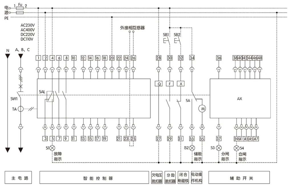
| Terminal Number | Function Description | Symbol | Explanation | Remarks |
| 1, 2 | Auxiliary power input: AC230V, AC400V, DC220V, DC110V |
SW1 | SW1 Universal Circuit Breaker | Customer self-provided |
| For DC power: 1 is (+), 2 is (-) | S1~S4 | Signal lamp | Customer self-provided | |
| 3, 4, 5 | Fault trip auxiliary contact, contact capacity: AC250V, 3A |
TA | Current transformer | |
| 20 | Grounding (PE) | SAL | Micro switch | Customer self-provided |
| 27, 28 | Undervoltage release | SB1 | Open button | Customer self-provided |
| 29, 30 | Shunt release | SB2 | Close button | |
| 31, 32 | Closing electromagnet | x | Closing electromagnet | |
| 33, 34, 35 | Motor-operated mechanism (motor energy storage), 37 connect green wire, 38 connect black wire, 39 connect red wire |
F | Shunt release | |
| 36~48 | Auxiliary contact terminal | Q | Undervoltage release | |
| M | Motor-operated mechanism | Customer self-provided | ||
| SA | Travel switch of motor-operated mechanism | Customer self-provided | ||
| Fu | Fuse | Customer self-provided | ||
| PE | Grounding | |||
| N | Neutral line (N phase) | |||
| A, B, C | Phase line | |||
| For customer optional use of AX auxiliary switch form | AX | Auxiliary switch | ||
Wiring diagram of secondary circuit for SW1-1600-6300 circuitbreakers equipped with H type intelligent controllers (auxiliary :switch default configuration: 4 changeover contacts)
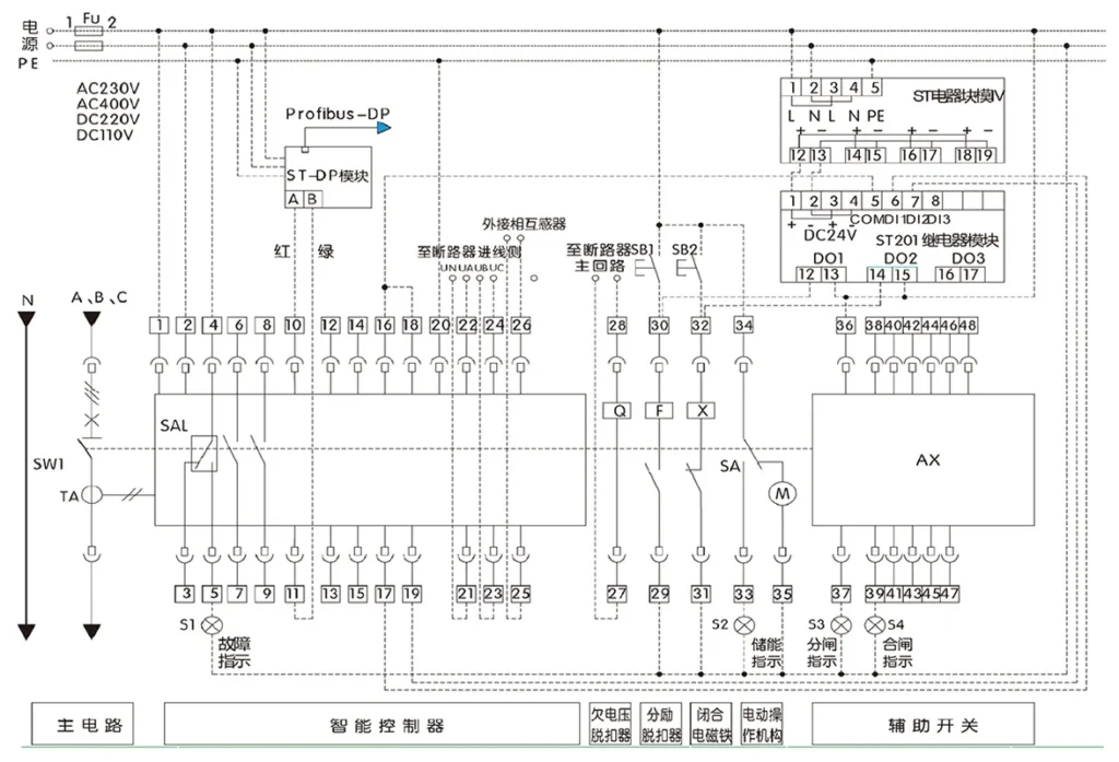
| Terminal Number | Function Description | Symbol | Explanation | Remarks |
| 1, 2 | Auxiliary power input: AC230V, AC400V, DC220V, DC110V |
SW1 | SW1 Universal Circuit Breaker | Customer self-provided |
| For DC power: 1 is (+), 2 is (-) | S1~S4 | Signal lamp | Customer self-provided | |
| 3, 4, 5 | Fault trip auxiliary contact, contact capacity: AC250V, 3A |
TA | Current transformer | |
| 10, 11 | Communication interface output, 10 is (+), 11 is (-) |
SAL | Micro switch | Customer self-provided |
| 12~15 | DO1, Programmable signal output, contact capacity: AC250V, 3A |
SB1 | Open button | Customer self-provided |
| 14, 15 | DO2, Programmable signal output, contact capacity: AC250V, 3A |
SB2 | Close button | Customer self-provided |
| 16, 17 | DO3, Trip signal output, contact capacity: AC250V, 3A |
X | Closing electromagnet | |
| 18, 19 | DO4, Closing signal output, contact capacity: AC250V, 3A |
F | Shunt release | |
| 20 | Grounding (PE) | Q | Undervoltage release | |
| 21, 22, 23, 24 | Voltage signal measurement, 21 connect N phase, 22 connect A phase, 23 connect B phase, 24 connect C phase |
M | Motor-operated mechanism | |
| 25, 26 | External N-phase transformer input | SA | Travel switch of motor-operated mechanism | Customer self-provided |
| 27, 28 | Undervoltage release | Fu | Fuse | Customer self-provided |
| 29, 30 | Shunt release | PE | Grounding | |
| 31, 32 | Closing electromagnet | N | Neutral line (N phase) | |
| 33, 34, 35 | Motor-operated mechanism (motor energy storage), 37 connect green wire, 38 connect black wire, 39 connect red wire |
A, B, C | Phase line | |
| 36~48 | Auxiliary contact terminal | AX | Auxiliary switch | |
| For customer optional use of AX auxiliary switch form | ST-DP Module |
Required for Profibus-DP communication | ||
| ST-DP Module |
Required for communication function | |||
| ST201 Relay Module |
Required for communication function | |||
الأبعاد (مم)
CQW2-1600 Series Fixed Type Overall Dimensions (Unit: mm)
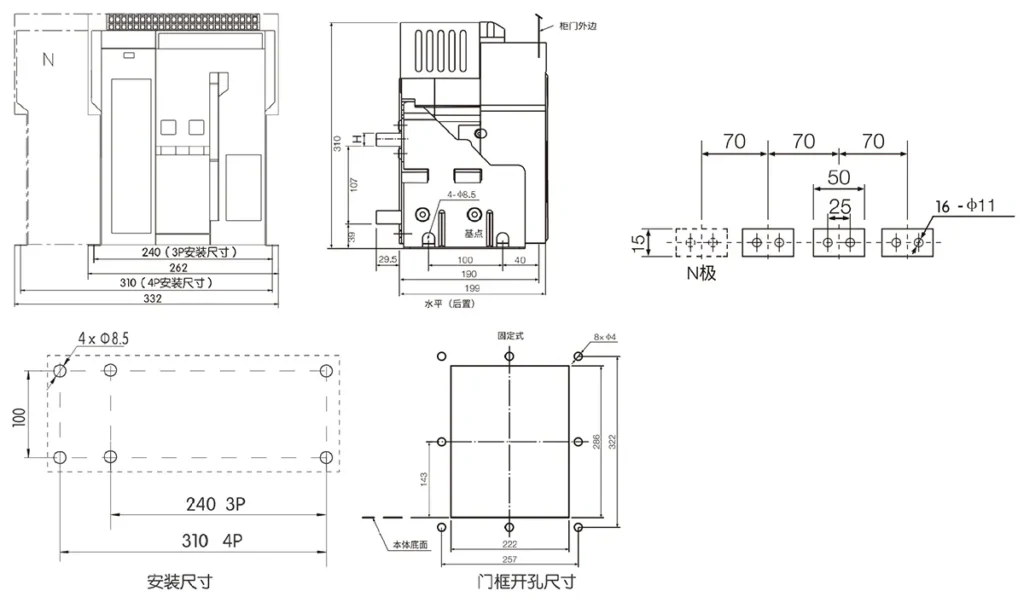
| Rated current | H (mm) |
| 200、400、630 | 6 |
| 800、1000 | 10 |
| 1250、1600 | 18 |
CQW2-1600 Series Drawout Type Installation Dimensions (Unit: mm)
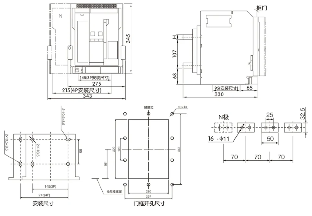
| Rated current | H (mm) |
| 200、400、630 | 6 |
| 800、1000 | 10 |
| 1250、1600 | 18 |
CQW2-1600 Series Fixed Type Overall Dimensions (Unit: mrm)
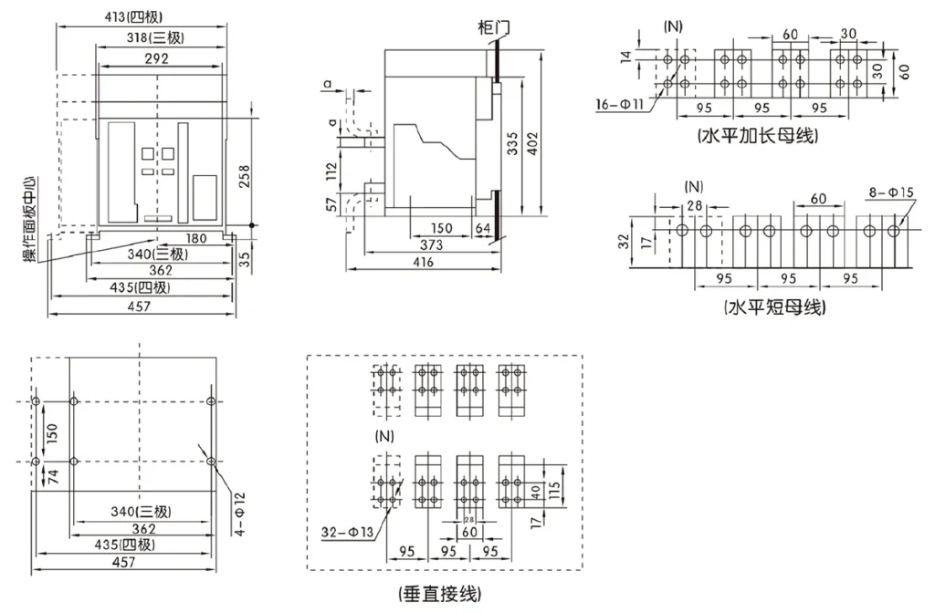
| In | a (mm) |
| 400~800A | 10 |
| 1000~1600A | 15 |
| 2000A | 20 |
CQW2-1600 Series Drawout Type Installation Dimensions (Unit: mm)
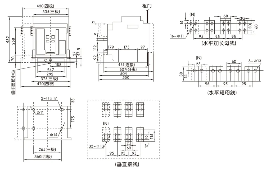
| In | a (mm) |
| 400~800A | 10 |
| 1000~1600A | 15 |
| 2000A | 20 |
CQW2-1600 Series Fixed Type Overall Dimensions (Unit: rnm)
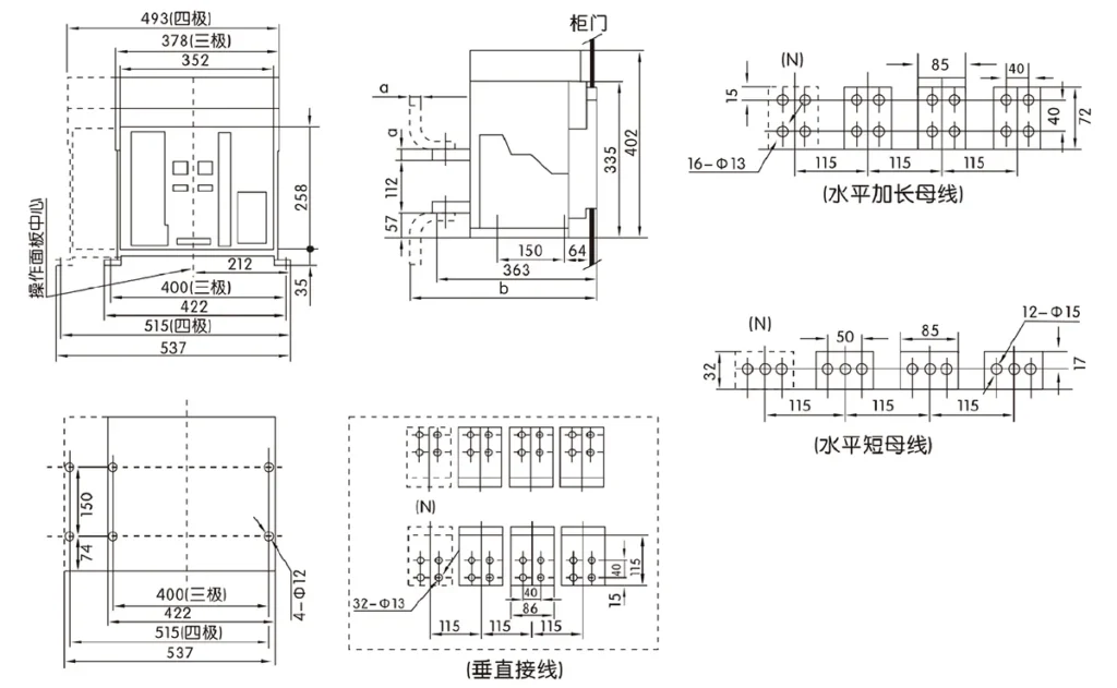
| In | a (mm) | b (mm) |
| 2000,2500A | 20 | 408 |
| 2900~3200A | 30 | 428 |
CQW2-1600 Series Drawout Type Installation Dimensions (Unit: mm)
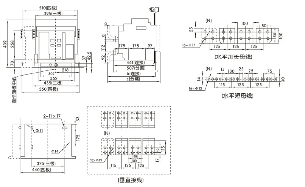
| In | a (mm) | b (mm) | c (mm) |
| 2000,2500A | 20 | 506 | 552 |
| 2900-3200A | 30 | 526 | 572 |
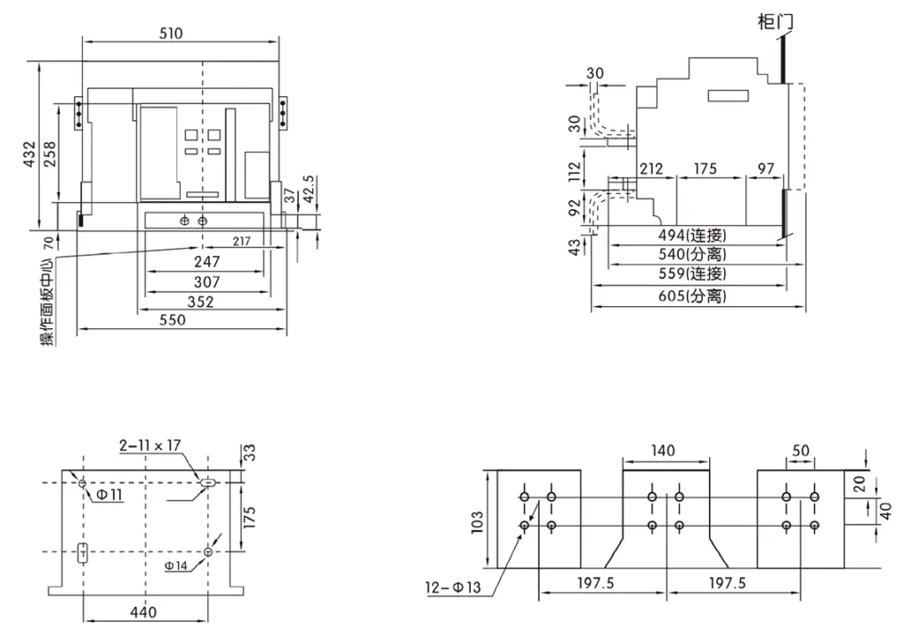
CQW2-4000 Series Drawout Type (3-Pole) Frame II Increased Capacity Type OvDimensions (Unit: mm)
CQW2-4000 Series Drawout Type (4-Pole) Overall Dimensions (Unit: mm)
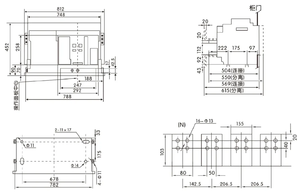
CQW2-6300 Series (In=5000A, 4000A) Drawout Type Overall Dimensions (Unit: mm)
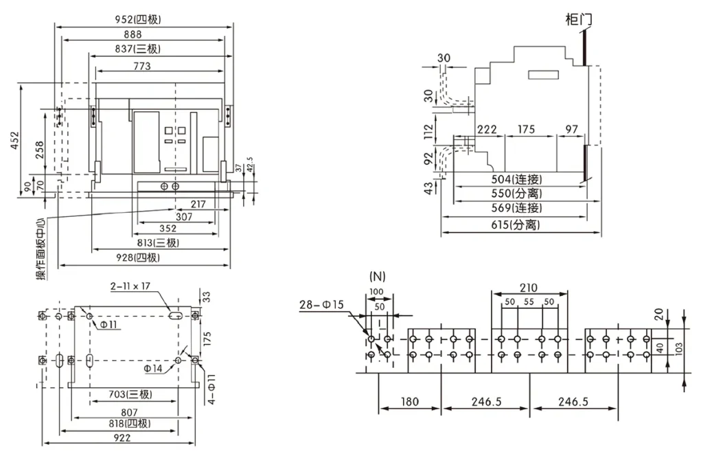
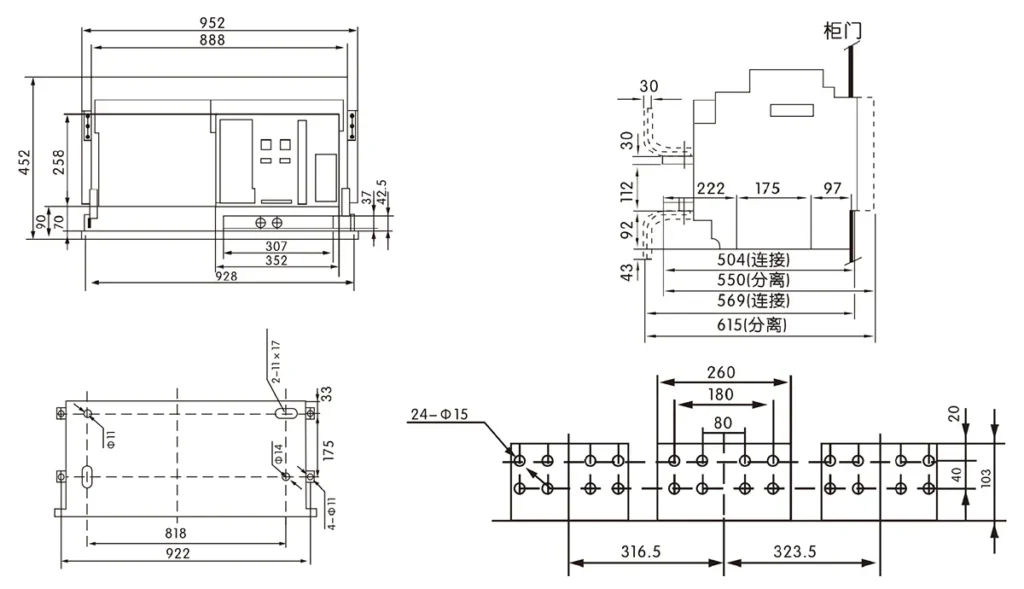
CQW2-6300 Series (In=6300A) Drawout Type (3-Pole) Overall Dimensions (Unit: mm)
CQW2 Series Enclosure Door Frame Outline and Irnstallation Dimensions (Unit: mm)
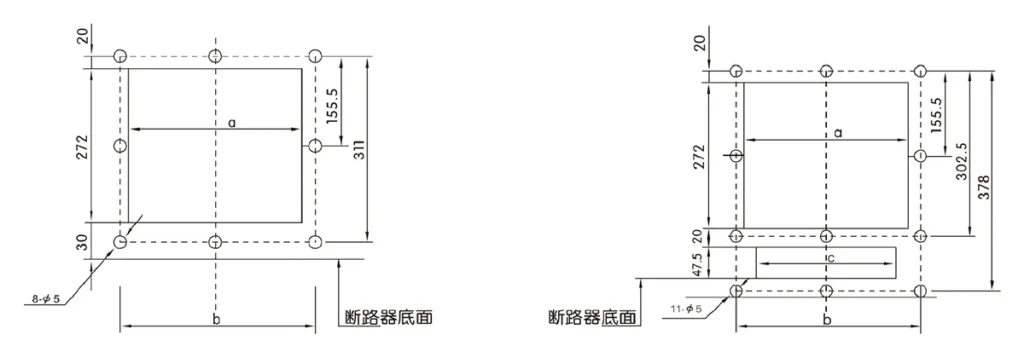
| Model number | a | b | c |
| CQW2-2000 | 304 | 345 | 263 |
| CQW2-3200, 4000/3P | 366 | 405 | 325 |
| CQW2-4000/4P | 304 | 345 | 263 |
| CQW2-6300 | 366 | 405 | 325 |
لماذا تختار CHAC
مع خبرة تصنيع تزيد عن 30 عامًا، وأكثر من 1100 موظف، وأكثر من 100 مليون عمود
بفضل طاقتها الإنتاجية السنوية ونظام الإنتاج الآلي 90%، توفر شركة CHAC طاقة إنتاجية مستقرة ومعايير صارمة
مراقبة الجودة لعملاء OEM/ODM العالميين. يدعم نظام التصنيع الداخلي الخاص بنا على المدى الطويل
تعاون مع العلامات التجارية الكهربائية والمستوردين والموزعين.

30+
سنوات الخبرة
متخصص في تصنيع المعدات الكهربائية منخفضة الجهد

1100+
الموظفين
فريق محترف يضمن جودة ثابتة والتسليم

١٠٠ مليون+
السعة السنوية للأعمدة
قدرة إنتاجية واسعة النطاق لتلبية الطلب العالمي

90%
الإنتاج الآلي
الأتمتة المتقدمة لتحقيق كفاءة واتساق عاليين
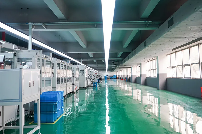
خط التجميع الآلي

مختبر اختبار
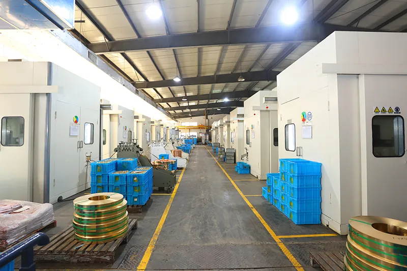
حقن وختم
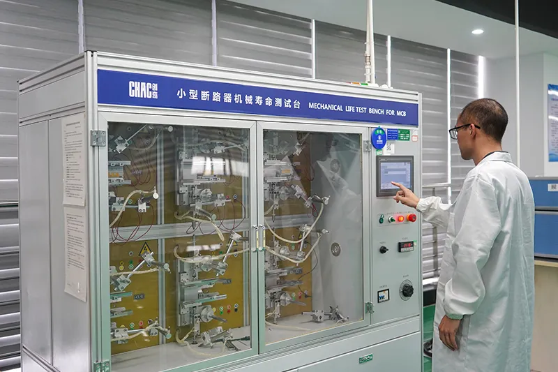
فحص الجودة



نظام صارم لمراقبة الجودة يضمن أن كل منتج يلبي المعايير العالمية.
ما الذي يمكننا تخصيصه؟
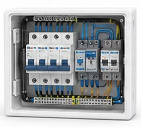
Flexible customization services are available for enclosure dimensions, component configuration,
branding and project requirements.

حَظِيرة
تصميم
أحجام وحاويات مخصصة وهياكل وتفاصيل تركيب.
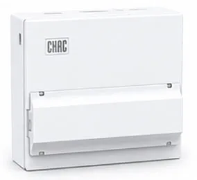

داخلي
إعدادات
خيارات مرنة لتخطيط داخلي وترتيب المكونات.

العلامة التجارية و
شعار
شعارات العلامة التجارية الخاصة، ولوحات الأسماء، وتحديد الهوية التجارية.

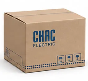
تعبئة وتغليف
تصميم
علب مخصصة، وملصقات، وأدلة، وحلول تغليف.

كهربائي
إعدادات
إعداد كهربائي مخصص بناءً على متطلبات التطبيق.

شهادة
دعم
دعم معايير السوق المستهدفة ومتطلبات الامتثال.
تنزيل
قواطع دوائر الهواء من سلسلة CQW2
نظرة عامة كاملة على مكونات كهربائية منخفضة الجهد ومرجع لاختيار المنتج.
هل تحتاج إلى وثائق فنية؟
اتصل بنا للحصول على أوراق البيانات، والشهادات، والرسومات، وإرشادات الاختيار، أو دعم مشاريع OEM/ODM.
CQW2 Product FAQ
Where is the CQW2 ACB used?
It is intended for large low-voltage distribution positions such as incomers, bus couplers or feeders when the selected frame, controller and installation arrangement are suitable.
How do I choose the frame and current?
Use design current, service conditions, short-circuit study, selectivity, poles, mounting type and controller functions. Frame size alone is not sufficient.
What is Icu?
Icu is the rated ultimate short-circuit breaking capacity under the applicable product standard. Confirm the test voltage and exact variant before using the value in a design.
Fixed or drawout mounting?
Choose from the installation and maintenance strategy, required isolation and switchboard design. Verify the matching cradle and interlocks.
What controller options are available?
The CQW2 record identifies standard, electronic and communication controller options. Confirm protection functions and control voltage for the order.
How should an ACB be commissioned?
Test insulation, primary and secondary circuits, trip functions, interlocks, racking positions and coordination settings with qualified personnel.
Confirm the Right CQW2 Configuration
Send the exact model, operating conditions, quantity, destination market and required documents. CHAC will review the request against the published product data.