Una scatola di derivazione che sporge dalla parete non costituisce sempre un problema di copertura. Dietro di essa, un dispositivo profondo, un connettore e un ingresso cavi posteriore possono trovarsi a occupare lo stesso spazio ristretto. Stringere ulteriormente le viti può mascherare il problema, ma allo stesso tempo sollecitare i conduttori o impedire al dispositivo di essere correttamente posizionato. Anche una parete sottile esclude la semplice soluzione di utilizzare una scatola più profonda. Questa guida spiega come individuare il reale vincolo di profondità, confrontare gli schemi dei prodotti e scegliere una configurazione ammissibile, evitando di confondere l’adattabilità fisica con una capacità di cablaggio accettabile.
A scatola elettrica poco profonda è un'opzione a profondità inferiore all'interno di una particolare famiglia di prodotti, e non una profondità standardizzata universale. Ad esempio, RACO elenca una scatola saldata a tre posti 952 con una profondità di 1-5/8 e una scatola a tre posti 942 con una profondità di 2-1/2. La fattibilità di entrambe dipende dal metodo di installazione, dallo spazio murario disponibile, dalla sporgenza del dispositivo e dal riempimento richiesto. Innanzitutto, misura la cavità della parete finita e l'intera disposizione dei dispositivi. Quindi confronta la scatola, il coperchio e gli accessori di ingresso specifici; non comprimere i conduttori né ricorrere a modifiche non approvate per far sembrare adeguato un involucro poco profondo.
Quale parte dell’installazione sta consumando la profondità?
Misurare dalla superficie finita fino all’ostacolo posto dietro la scatola prevista. La parete potrebbe contenere muratura, una flangia del montante, un altro impianto o un raccordo che impedisce di utilizzare l’intera profondità nominale. Una misura effettuata sulla sola struttura metallica potrebbe risultare fuorviante una volta posati piastrelle, pannelli e la ghiera di fissaggio.
Successivamente, separare la profondità della scatola dalla sporgenza installata del dispositivo. Anche i morsetti e i connettori, oltre al corpo del dispositivo, necessitano di spazio. Un ingresso posteriore potrebbe posizionare la curva del conduttore direttamente dietro la parte più profonda di un interruttore intelligente o di una presa con protezione GFCI. Passare a una diversa configurazione di ingresso consentita può fare la differenza, ma solo se le istruzioni relative alla scatola e al cablaggio lo permettono.
| Problema osservato | Dimensione da controllare | Confine di decisione |
|---|---|---|
| La scatola colpisce la parete posteriore | Profondità esterna e sporgenza del raccordo | Scegli un recinto autorizzato che sia adatto. |
| Il dispositivo non si inserisce. | Profondità di installazione del dispositivo e posizione del connettore | Non forzarlo con le viti. |
| Il cablaggio è affollato. | Volume segnato e riempimento effettivo | La chiusura fisica non dimostra la conformità. |
| La copertina è posizionata in modo errato. | Posizione del rivestimento finale e anello di corrispondenza | Verifica l'assemblaggio approvato |
Come si confrontano i modelli poco profondi con quelli più profondi?
Il Prodotto RACO 952 è descritta come una scatola saldata a tre moduli con una profondità di 1-5/8. La Prodotto RACO 942 è una scatola saldata a tre posti con una profondità di 2-1/2. La differenza è di 7/8 tra questi due esempi pubblicati. Queste voci, verificate il 19 ottobre 2026, stabiliscono un confronto reale delle profondità senza pretendere che tutte le scatole poco profonde abbiano le stesse dimensioni.
Il profondità della scatola di giunzione Le unità assemblate devono includere anche il coperchio selezionato e gli accessori esterni, qualora influenzino l’installazione. Il volume nominale di una scatola deve essere desunto direttamente dal relativo certificato o dalla marcatura; non deve essere calcolato moltiplicando le dimensioni esterne, poiché la costruzione e le caratteristiche interne influiscono sullo spazio utile.
| Opzione | Potenziale motivo per prenderlo in considerazione | Verifica richiesta |
|---|---|---|
| Scatola elencata meno profonda | Cavità limitata dietro la parete | Autorizzazione del dispositivo e riempimento calcolato |
| Scatola compatibile con Deeper | Più spazio dietro un dispositivo profondo | Distanziamento dalla parete, montaggio e disposizione degli ingressi |
| Disposizione superficiale consentita | Cavità nascosta insufficiente | Approved box, fittings and exposed installation |
| Different suitable device | Installed device projection is the constraint | Electrical function and mounting compatibility |
| Redesigned wiring arrangement | Connectors or entries block access | Permitted wiring method and accessible connections |
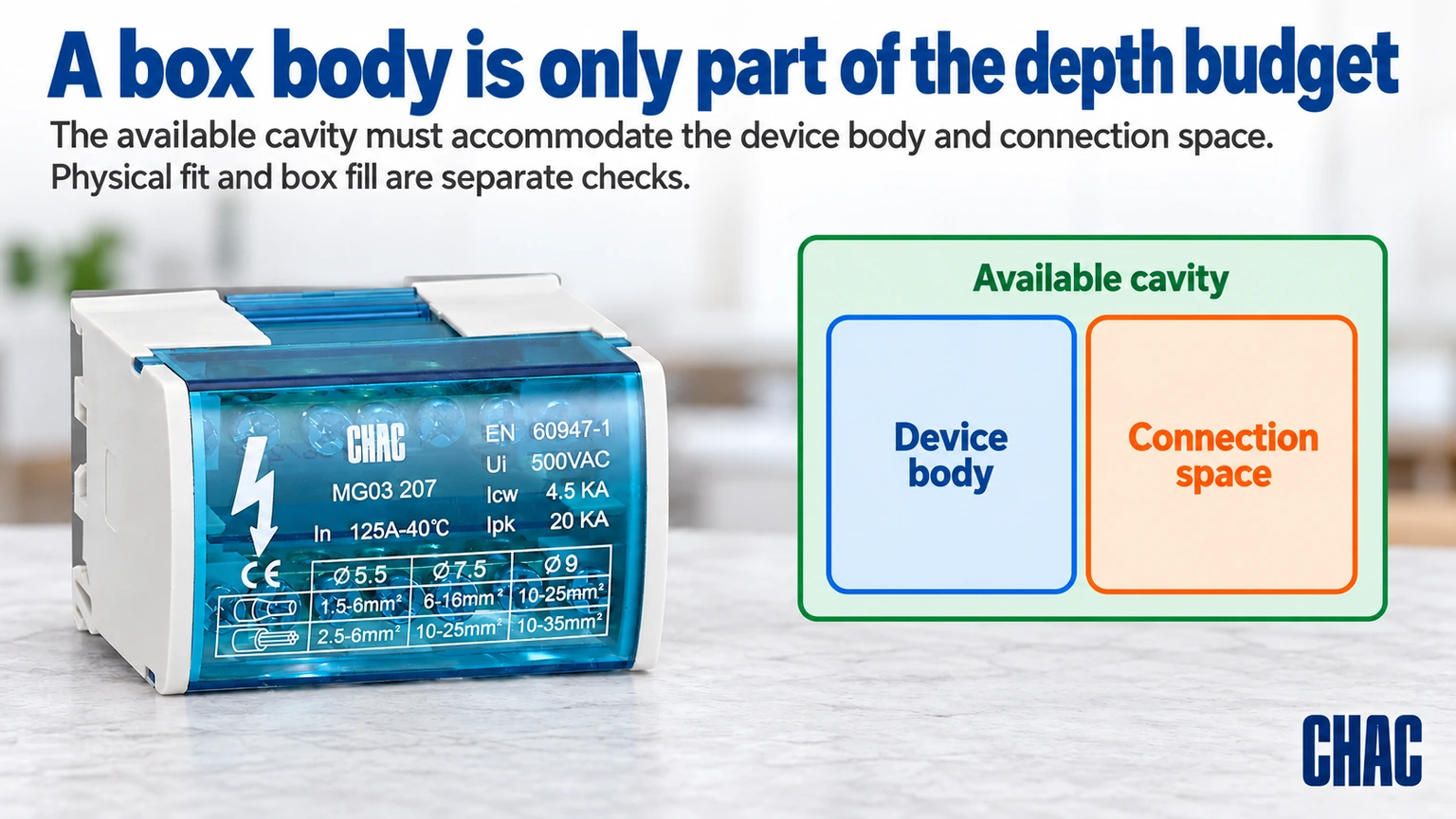
How do you build a useful depth budget without confusing it with box fill?
Draw the device and entry fittings from a shared mounting plane, using the actual internal envelope rather than the box’s nominal outside depth. For a simplified hypothetical example, assume 2.0 in of usable depth behind the mounting plane and a device projecting 1.4 in into it. That leaves 0.6 in in the same rearward direction before considering a connector, conductor route or other obstruction. None of those assumed dimensions describes a particular product.
The remaining 0.6 in is not a permitted conductor allowance or a box-fill calculation. Parts can occupy different regions, and their envelopes may overlap differently from a simple stack. Check the proposed routes on the assembly drawing and, where necessary, a de-energized sample. Record the first actual interference. This identifies whether the limiting item is the box shell, the device, an entry fitting or the wiring arrangement, rather than treating every seating problem as insufficient total volume.
Can a shallow box pass fill checks and still be difficult to use?
Yes. Required volume is one acceptance condition; conductor routing and assembly access are another. A device can occupy the central space while connectors sit at the sides, but that arrangement must remain practical without damaging insulation or exceeding product instructions. It should not depend on a precise fold that cannot be reproduced during maintenance.
Apply the adopted box-fill rules to the actual circuit. Different items can have different counting treatment, and grounding-conductor provisions depend on the applicable rules. A generic statement that a box holds a certain number of wires is incomplete when devices, clamps or other components are added. Have the calculation checked for the intended installation rather than treating an online capacity example as a permit-ready design.
When should the installation be redesigned?
If no suitable box can meet both the cavity limit and the wiring requirement, the constraint is real. A permitted surface box, a relocated device or another approved arrangement may be necessary. An extension ring is not automatically suitable for every enclosure or wall system; confirm the manufacturer’s compatibility and how the finished assembly is approved.
Do not remove required box parts, cut away a mounting feature or leave connections behind an inaccessible cover to gain space. Material choice must also remain suitable for the wiring system and environment. Metal requires the applicable bonding arrangement, while nonmetallic construction does not remove the need for correct entries, fastening and any wall-assembly conditions.
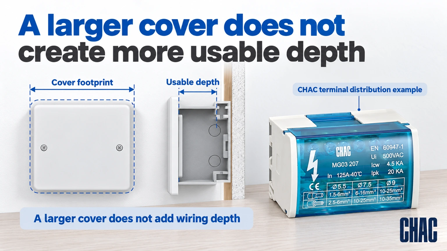
What must an extension proposal show before it solves the depth problem?
Request the exact box, extension or raised cover, device mounting arrangement and compatible fasteners as one proposal. Ask which documented volume may be included in the applicable fill evaluation and where the finished device plane will sit. Do not assume that a raised decorative face creates approved wiring space, or that every extension can be attached with longer device screws.
Also check any required bonding, cover engagement, wall-assembly conditions and entry access after the change. A proposal may solve the rear clearance while creating an unacceptable front projection or preventing the cover from seating. Mark both positions on the drawing and obtain the relevant manufacturer instructions. If the proposed combination has no supporting compatibility information, retain the unresolved status and evaluate another permitted arrangement rather than describing the extension as a completed repair.
What should be confirmed before ordering a replacement box?
Record the available cavity, finished-wall position, device model, conductor and connector arrangement, mounting method and required approval. Request the replacement’s drawing and installation instructions, then compare the complete assembly. This makes electrical box depth a defined requirement rather than a guess based on the old cover.
di CHAC distribution junction box connection assembly is a terminal and bus connection product, not a shallow outlet box. Its documented dimensions are relevant to cabinet layouts that use that function. For related projects, consult the distribution and control product range while keeping the wall enclosure and device specification separate.
What are the common questions about shallow electrical boxes?
What is the shallowest electrical box you can get?
The answer depends on the product family and intended installation. Choose from approved models that meet the wiring and device requirements, rather than selecting the smallest advertised depth alone.
What is the minimum depth of an electrical box?
There is no single minimum suitable for every device and circuit. Check the applicable installation rules, device instructions, capacity and enclosure approval.
What are shallow electrical boxes used for?
They can serve installations where the available cavity is limited, provided the chosen box remains suitable for the devices, wiring method, fill and mounting conditions.
What are the dimensions of a shallow electrical box?
They are model-specific. The cited RACO 952 example is 1-5/8 inches deep, but that does not define every shallow box or its required opening.
What are the standard sizes for shallow electrical box?
Compare the exact height, width, depth and capacity within the chosen manufacturer range. The shallow label alone does not identify these values.
How deep should shallow electrical box be for the wiring inside?
Deep enough for the permitted device and conductor arrangement while meeting fill requirements, and shallow enough to fit the real cavity. If both cannot be met, redesign the installation rather than forcing the wiring.
Referenze
- Hubbell RACO 952: three-gang 1-5/8-inch-deep box; accessed October 19, 2026
- Hubbell RACO 942: three-gang 2-1/2-inch-deep box; accessed October 19, 2026
- Hubbell RACO enclosure families and accessories; accessed October 19, 2026
Conclusione
A shallow-box problem is solved by identifying the space constraint, not by hiding it behind a larger faceplate. Check the finished cavity, the installed device and the conductor arrangement before comparing replacement enclosures. Then verify capacity, mounting, entries and any approved cover or extension as one assembly. If the required wiring cannot fit appropriately, change the installation arrangement rather than crushing conductors or modifying the box without approval. Model-specific depth examples help compare options, but they do not establish a universal minimum or guarantee device compatibility. CHAC provides documented connection and distribution components for relevant cabinet applications. Use the exact model information for those functions and a separately verified wall-box specification where the project needs an outlet enclosure.
Per i disegni del modello e la documentazione di progetto pertinenti, Contattare CHAC con i requisiti del circuito..