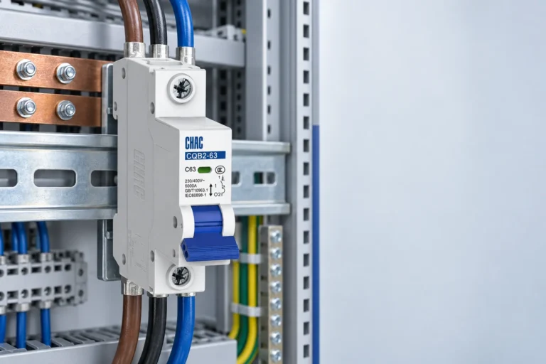
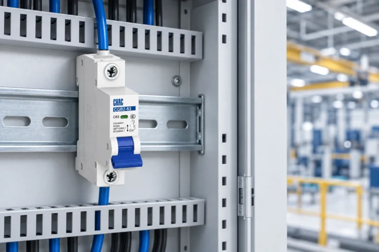
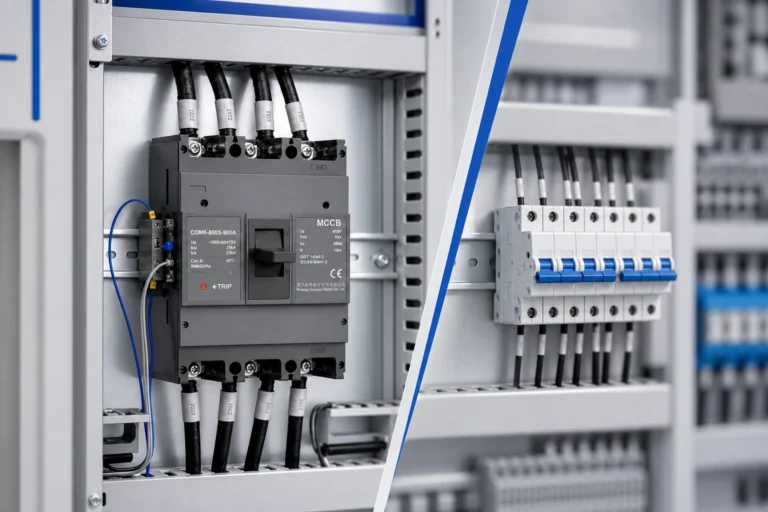
Para os fabricantes de quadros, a escolha entre um disjuntor (MCB) unipolar e bipolar começa pelos condutores que o circuito deve desligar e proteger — e não pela largura do painel ou por uma designação familiar. Um dispositivo 1P atua sobre um polo; um dispositivo 2P tem dois polos interligados. Verifique se o produto selecionado comuta, protege, ou comuta e protege cada condutor, confirmando depois a disposição do circuito, as normas locais e a documentação do produto antes da aprovação.
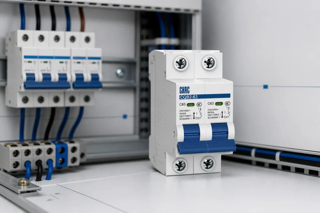
Parte 1. Começar pelos condutores que o circuito deve desligar
A contagem de polos descreve a disposição de um dispositivo; por si só, não confirma como uma determinada instalação deve ser protegida. Comece pelo diagrama unifilar e identifique todos os condutores que devem abrir em simultâneo para a função de comutação ou seccionamento exigida pelo circuito.
O próximo controlo é separado: identifique quais os condutores que requerem proteção contra sobrecorrente. Uma etiqueta de produto, um filtro de catálogo e uma comparação visual não substituem o esquema de ligações, as marcações e a documentação técnica do modelo selecionado.
| Pergunta de revisão | Porque é que muda a escolha | Evidência para guardar com o processo do painel |
|---|---|---|
| Que condutores alimentam a carga? | Define se o circuito tem um ou dois condutores a ser abertos em conjunto | Diagrama unifilar e designação de circuitos |
| Quais os condutores que devem ser comutados? | Separa as necessidades de comutação das necessidades de proteção contra sobrecorrente | Regra de projeto aplicável e diagrama do dispositivo |
| Que postes estão protegidos? | Impede tratar toda a construção bipolar como idêntica | Folha de dados e marcação do modelo selecionado |
| O dever é AC ou DC? | A adequação para CA não estabelece a adequação para CC | Documentação de dever nominal para o dispositivo exato |
Para uma vista mais abrangente de termos como postes, curvas e marcações, utilize isto Guia de tipos e especificações de disjuntores (MCB) em simultâneo com a documentação do produto final.
Parte 2. O que um disjuntor unifilar faz — e não faz
Um disjuntor miniatura (MCB) unipolar destina-se a comutar e proteger um condutor na disposição do circuito para a qual foi especificado. Isso pode ser um ponto de partida adequado quando o projeto do circuito, as regras aplicáveis e a documentação do dispositivo selecionado suportam uma disposição unipolar.
A limitação é igualmente importante: a comutação unipolar não se transforma em isolamento de dois condutores pelo facto de um neutro próximo ou outro condutor estar presente. O esquema do painel deve mostrar o que permanece ligado quando o dispositivo está aberto.
| Ponto de revisão unipolar | O que confirmar antes da seleção |
|---|---|
| Arranjo de circuitos | O condutor atribuído ao poste e a função prevista do circuito |
| Mudança de expetativa | Se a abertura de um condutor satisfaz a abordagem de isolamento documentada |
| Expectativa de proteção | A função de sobrecorrente do polo conforme declarado na documentação selecionada |
| Interface do painel | Montagem, terminais, acessórios e etiquetagem na montagem real |
Esta comparação não prescreve uma lista de aplicação universal. Um fabricante de quadros elétricos deve documentar primeiro a função do circuito, comparar de seguida o pedido com as regras de instalação aplicáveis e com as instruções do disjuntor (MCB) selecionado.
Parte 3. Porque é que 1P+N Precisa da Sua Própria Verificação
A designação 1P+N merece uma linha separada na lista de materiais. É habitualmente utilizada para uma construção que comuta a fase e o neutro em conjunto, enquanto a função de sobrecorrente está associada ao polo da fase; contudo, a disposição exata é uma questão de seleção de produto, e não uma abreviatura que possa ser assumida apenas a partir da designação.
Essa distinção é importante porque 1P+N e 2P podem cumprir requisitos de corte e protecção diferentes. Peça ao fornecedor o diagrama do dispositivo, a função dos pólos, a norma aplicável e o esquema de alimentação pretendido antes de substituir um pelo outro.
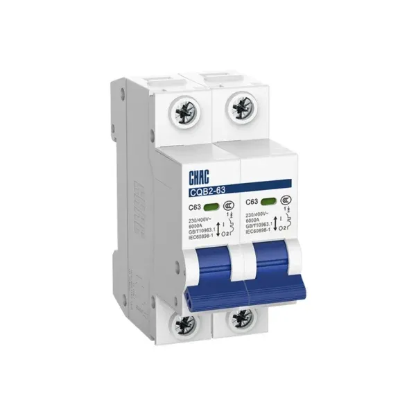
Recomendado pelo CHAC MCB:
Disjuntor Miniatura CQB2-63 Para Sistemas de Energia | CHAC Electric
Importante: Não utilize um disjuntor miniatura (MCB) de CA num circuito de CC apenas por ter um ou dois polos. A norma IEC 60898-2 estabelece requisitos adicionais para disjuntores monopolares e bipolares adequados para funcionamento em CA e CC; o produto exato deve ser explicitamente dimensionado e documentado para a utilização pretendida.IEC 60898-2:2016)
Utilize o Guia da placa de caraterísticas do disjuntor miniatura para preparar perguntas, mas utilize a documentação do produto selecionada para tomar a determinação final.
Parte 4. Quando um Disjuntor Bipolar Pertence à Revisão
Um disjuntor miniatura (MCB) bipolar é relevante quando o circuito exige que dois condutores sejam abertos em simultâneo ou requer a construção bipolar documentada pelo projeto. Os dois polos estão mecanicamente ligados, mas a respetiva disposição de polos protegidos ainda necessita de confirmação através da documentação exata do dispositivo.
Considere o prompt de revisão em vez de uma regra geral:
- O circuito contém dois condutores que devem desligar em conjunto?
- A documentação do projeto exige a desmultiplicação simultânea ou uma disposição específica de polos?
- O produto selecionado indica como cada polo é comutado e protegido?
- O regime nominal, a norma e as condições de instalação do dispositivo correspondem aos requisitos do projeto?
A norma IEC 60898-1 fornece o enquadramento da norma de produto para disjuntores em corrente alterna para instalações domésticas e análogas, dentro do seu âmbito definido. Os projetos destinados a pessoas instruídas ou qualificadas podem exigir um enquadramento normativo diferente, pelo que a especificação do projeto – e não o título do artigo – determina o que é aplicável.
Parte 5. Transformar a Comparação numa Decisão de Painel
Traduzir a questão do poste num caminho de seleção documentado. A tabela abaixo mantém a comutação, a proteção e as evidências de aquisição separadas para que uma cotação não substitua discretamente uma decisão de circuito.
| Ponto de decisão | Revisão 1P | Revisão por pares | Enviar com pedido de cotação |
|---|---|---|---|
| Condutores do circuito | Identifique o único condutor ligado ao polo do disjuntor | Identifique ambos os condutores e explique porque razão devem abrir em conjunto | Esquema unifilar e identificador de circuito |
| Função de comutação | Confirmar que a abertura unipolar corresponde ao projeto documentado | Confirmar que a abertura simultânea bipolar é necessária | Função de funcionamento e isolamento obrigatória |
| Proteção de postes | Verificar a função de polo protegido a partir do modelo selecionado | Verifique a função de polo protegido de cada polo a partir do modelo selecionado | Ficha técnica, esquema de ligações e código do modelo |
| Dever e padrão | Confirme a aplicação documentada do dispositivo selecionado | Confirme a aplicação documentada do dispositivo selecionado | dever de CA/CC, norma aplicável, requisito do mercado-alvo |
| Restrições de montagem | Verifique o esquema real do painel e as interfaces | Verifique o esquema real do painel e as interfaces | Pormenor de montagem, acessórios, rotulagem e quantidade |
Esta abordagem também evita um erro comum de aprovisionamento: comparar apenas a corrente nominal e o número de polos, omitindo o esquema de circuitos e a documentação necessária. A escolha final deve basear-se no circuito, na carga, nas normas locais e no ficheiro do produto selecionado.
Parte 6. Escolha uma Rota de Produto Apenas Após os Inputs Estarem Definidos
Recomendação de produto
Assim que os dados do projeto estiverem completos, o publicado Família de disjuntores miniatura CQB2-63 é uma rota de primeira parte relevante para debater porque a sua página lista opções das famílias 1P, 1P+N e 2P. Não se trata de uma afirmação de que qualquer opção nessa página se adapta a um painel específico.
Para contexto da categoria, reveja a da CHAC Electric Categoria de produtos MCB e o mais abrangente Eletrodomésticos de Terminal gama. Não escolha um substituto genérico apenas porque parece semelhante ou tem o mesmo número de polos; a disposição exigida de polos protegidos, o serviço nominal, a norma e a adaptação ao painel devem ser todos verificados.
Para uma discussão com um OEM, envie o diagrama unifilar, a disposição dos condutores, o serviço pretendido, os requisitos de documentação, as limitações do painel e as necessidades de marca ou embalagem através de personalização de produtos elétricos terminais. Isso confere ao fornecedor uma base passível de revisão para uma discussão sobre a rota do produto.
Parte 7. Limite de Ajuste: Quando a Contagem de Polos Não É a Decisão Final
Limite de Ajuste: este guia é útil para comparações preliminares, especificação de painéis e comunicação com fornecedores. Não é adequado para instruções de trabalho em direto, coordenação de proteção final, interpretação de regulamentos locais ou seleção de CC sem uma classificação explícita para o serviço de CC pretendido.
O número de polos é apenas um campo numa decisão de lançamento. A seleção final deve ser verificada em relação ao circuito e à carga, aos regulamentos locais, ao projeto do painel, à norma aplicável e à documentação atual do produto selecionado.
Quando o desenho e o conjunto de requisitos estiverem prontos, contactar CHAC Electric com a disposição de pólos exigida e o pacote de evidências para uma discussão de produto.
FAQs
Qual é a diferença básica entre um disjuntor (MCB) 1P e 2P?
Um disjuntor miniatura (MCB) monopolar (1P) tem um polo para o condutor que lhe é atribuído. Um disjuntor miniatura (MCB) bipolar (2P) tem dois polos mecanicamente ligados que abrem em simultâneo. A documentação do produto selecionado deve ainda confirmar a função e o esquema de proteção de cada polo.
O 1P+N é o mesmo que 2P?
Não. Uma etiqueta 1P+N é habitualmente associada a corte de fase e neutro com proteção contra sobrecorrente no polo de fase, enquanto um dispositivo 2P pode ter uma disposição de polos protegidos diferente. Confirme tanto o esquema de ligações como as marcações do produto antes de os tratar como alternativas.
Uma etiqueta 2P prova que ambos os polos estão protegidos?
Não. Apenas a contagem de polos não estabelece como cada polo está protegido. Solicite a ficha técnica do modelo selecionado e as informações de cablagem, depois compare-os com o requisito do circuito.
Pode um disjuntor miniatura (MCB) de CA ser utilizado num circuito de CC?
Apenas quando o dispositivo exato estiver expressamente classificado e documentado para o serviço CC pretendido. A norma IEC 60898-2 aborda requisitos adicionais para disjuntores CA/CC unipolares e bipolares elegíveis, mas não torna qualquer disjuntor miniatura (MCB) CA adequado para CC.
Quais são as normas que um montador de quadros deve consultar para um pedido de disjuntor (MCB)?
Comece pela regra de norma e de instalação nomeada nos documentos do projeto. A IEC 60898-1 abrange os disjuntores de CA para instalações domésticas e análogas dentro do seu âmbito, enquanto a IEC 60947-2 constitui uma norma de disjuntores de baixa tensão no contexto de pessoas instruídas ou qualificadas. O requisito do projeto e os documentos do modelo selecionado determinam a base final.
O que deve ser incluído num pedido de cotação (RFQ) para um disjuntor miniatura (MCB)?
Inclua o diagrama unifilar, a disposição da alimentação e dos circuitos, os condutores a comutar, a expectativa de polos protegidos, o serviço em CA ou CC, a norma aplicável, a evidência do modelo selecionado exigida, as restrições do painel e qualquer pedido de marca ou embalagem.
Quando é que este guia não é suficiente para a seleção final?
Não é suficiente quando o projeto requer coordenação final, interpretação de códigos locais, orientação de trabalho em tempo real ou aprovação específica de um modelo. Essas decisões exigem informações reais sobre o circuito e a carga, regras locais e a documentação do produto selecionado.
Referências
- IEC 60898-1:2015+AMD1:2019 — disjuntores para instalações domésticas e análogas em corrente alterna
- IEC 60898-2:2016 — requisitos adicionais para disjuntores unipolares e bipolares CA/CC elegíveis
- IEC 60947-2:2024 — aparelhagem de baixa tensão — Parte 2: Disjuntores
- Discussão do Electronics Stack Exchange sobre questões de 1P, 1P+N e isolamento