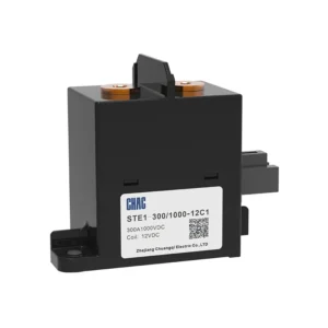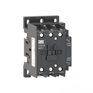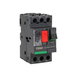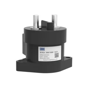


سلسلة موصلات التيار المتبادل ذات الخدمة الشاقة CQC1 والملحقات
ال سلسلة موصلات التيار المتبادل ذات الخدمة الشاقة CQC1 والملحقات is a CHAC AC contactor for remote switching and motor control. The page keeps the model-specific technical table and original product images so buyers can verify voltage, current, configuration, mounting and applicable standards before ordering. Final suitability depends on the complete circuit, installation method and destination-market rules.
Product Overview
CQC1 Series High-Duty AC Contactor and Accessories is a AC contactor intended for remote switching and motor control. The current product record identifies it for motor starters, HVAC and automation panels. Use the exact model variant and preserved technical source as the basis for procurement rather than assuming that every family member has the same rating.
Verified source summary: Model and Meaning Note 1: 09A~95A is in the form of auxiliary contact, and 115A~800Aisconventional without auxiliary10 indicates three normally open main contacts and one normally open auxiliary contact (32A and below)01 represents three normally open main contacts and one normally closed auxiliary contact (32A and below)11 represents three normally open main contacts, one normally open and one normally closed auxili
Key Features
Typical Applications
Typical use can include motor starters, HVAC and automation panels when the project confirms system voltage, current, fault or surge exposure, conductor and enclosure requirements, and the selected variant’s installation instructions. This page does not replace the project design or the authority having jurisdiction.
Applications and Selection Guide
Use the following decision points with the preserved model data. Product-family descriptions explain intent, but the exact technical table controls the ordered variant.
| Selection point | سلسلة موصلات التيار المتبادل ذات الخدمة الشاقة CQC1 والملحقات | What the project must confirm |
|---|---|---|
| تطبيق | AC Contactor projects | Confirm the actual system and environment |
| Selection basis | remote switching and motor control | Use the exact model and technical table |
| Installation | Follow the model instructions | Check mounting, clearances and termination |
| Compliance | Use the listed standard where applicable | Verify edition, scope and destination rules |
| Adjacent product | Evaluate the related CHAC family where function differs | Do not substitute without engineering review |
Function
remote switching and motor control
Match the protection or switching function to the system.
إعدادات
Model-specific options
Confirm current, voltage, poles, terminals or accessories from the table.
Installation
Mechanical and electrical fit
Check enclosure, mounting, wiring space and maintenance access.
Project evidence
Documents and test records
Retain the approved drawing, technical sheet and commissioning record.
Ordering Guide
- State the exact model and variant.
- Provide the system voltage, current, frequency and load or protection function.
- Confirm mounting, terminals, accessories, enclosure and environmental conditions.
- Share quantity, destination market and required technical documents.
Installation and Coordination Checks
- Verify the model’s ratings and connection arrangement against the project drawings.
- Check conductor, busbar, enclosure, clearances and tightening requirements using the product documentation.
- Coordinate upstream and downstream protection or control devices where applicable.
- Use qualified personnel for installation, testing, isolation and maintenance.
Model and Meaning

Note 1: 09A~95A is in the form of auxiliary contact, and 115A~800Aisconventional without auxiliary10 indicates three normally open main contacts and one normally open auxiliary contact (32A and below)01 represents three normally open main contacts and one normally closed auxiliary contact (32A and below)11 represents three normally open main contacts, one normally open and one normally closed auxiliary contact (40~95A).
Appearance and installation dimensions
CQC1-09 12、18、25、32
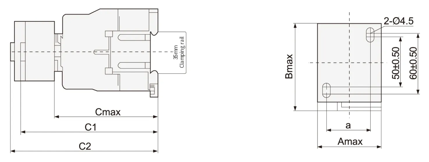
| Contactor model | Amax | Bmax | Cmax | a | C1 | C2 |
| CQC1-09、12 | 47 | 76 | 82 | 35±0.50 | 113 | 133 |
| CQC1-18 | 87 | 118 | 138 | |||
| CQC1-25 | 57 | 86 | 95 | 40±0.50 | 126 | 146 |
| CQC1-32 | 100 | 131 | 151 |
Note: C1:CQC1+F4 C2:CQC1+S4
CQC1-40、50、65、80、95
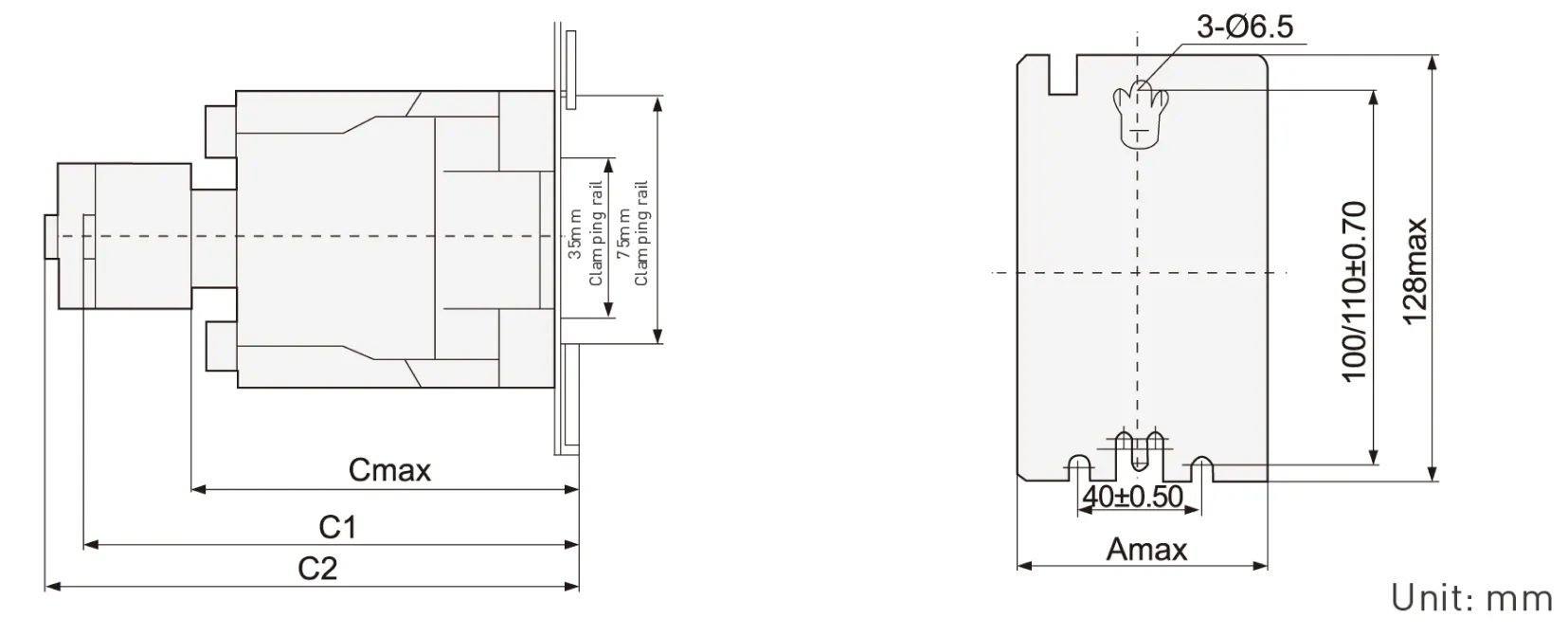
| Contactor model | Amax | Cmax | C1 | C2 |
| CQC1-4011-6511 | 77 | 116 | 145 | 165 |
| CQC1-8011~9511 | 87 | 127 | 175 | 195 |
Note:C1:CQC1+F4 C2:CQC1+S4
C0C1-115~330 overall dimensions and installation dimensions [tolerance: ± 1mm]

| CQC1 | a | P | Q | Q1 | S | Φ | f | b | b1 | M | N | c | L | G | H | Φ1 | G1 | Z | Y | X1 | |
| ≤500V | >500V | ||||||||||||||||||||
| 115 | 163.5 | 37 | 29.5 | 60 | 20 | M6 | 131 | 162 | 137 | 147 | 124 | 171 | 107 | 80 | 120-106 | 6.5 | 106 | 13.5 | 44 | 10 | 15 |
| 150 | 163.5 | 40 | 26 | 57.5 | 20 | M8 | 131 | 170 | 137 | 150 | 124 | 171 | 107 | 80 | 120-106 | 6.5 | 106 | 13.5 | 44 | 10 | 15 |
| 185 | 168.5 | 40 | 29 | 59.5 | 20 | M8 | 130 | 174 | 137 | 154 | 127 | 181 | 113.5 | 80 | 120-106 | 6.5 | 111 | 13.5 | 44 | 10 | 15 |
| 225 | 168.5 | 48 | 21 | 51.5 | 25 | M10 | 130 | 197 | 137 | 172 | 127 | 181 | 113.5 | 80 | 120-106 | 6.5 | 111 | 13.5 | 44 | 10 | 15 |
| 265 | 205 | 48 | 39 | 66.5 | 25 | M10 | 147 | 203 | 145 | 180 | 147 | 213 | 141 | 96 | 120-106 | 6.5 | 140 | 20.5 | 38 | 10 | 15 |
| 330 | 213 | 48 | 43 | 74 | 25 | M10 | 147 | 209 | 145 | 184 | 158 | 219 | 145 | 96 | 120-106 | 6.5 | 154.5 | 20.5 | 38 | 10 | 15 |
Note: f is the space required for coil replacement
X1 is the minimum electrical clearance [Flying Fox distance)the same as below
CQC1-400-500 overall dimensions and installation dimensions(tolerance: ± 1mm)
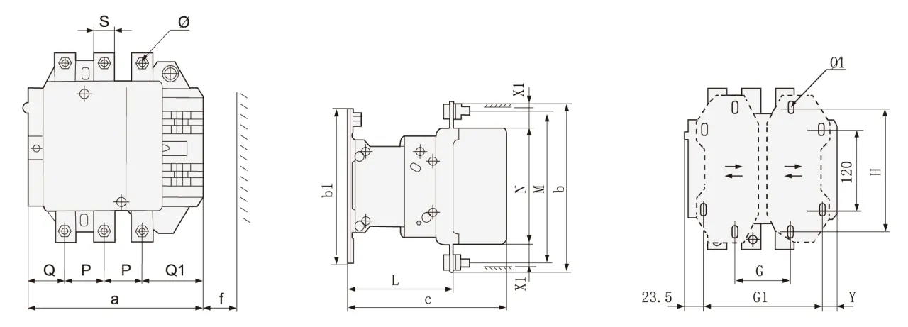
| CQC1 | a | P | Q | Q1 | S | Φ | f | b | b1 | M | N | c | L | G | G1 | Φ1 | H | Y | X1 | |
| ≤500V | >500V | |||||||||||||||||||
| 400 | 213 | 48 | 43 | 74 | 25 | M10 | 151 | 206 | 209 | 181 | 158 | 219 | 145 | 80(66-102) | 170(156-192) | 8.5 | 180 | 19.5 | 15 | 20 |
| 500 | 233 | 46 | 46 | 77 | 30 | M10 | 169 | 238 | 209 | 208 | 172 | 232 | 146 | 80(66-102) | 170(156-210) | 8.5 | 180 | 39.5 | 15 | 20 |
CQC1-630-800 overall dimensions and installation dimensions(tolerance: ± 1mm)
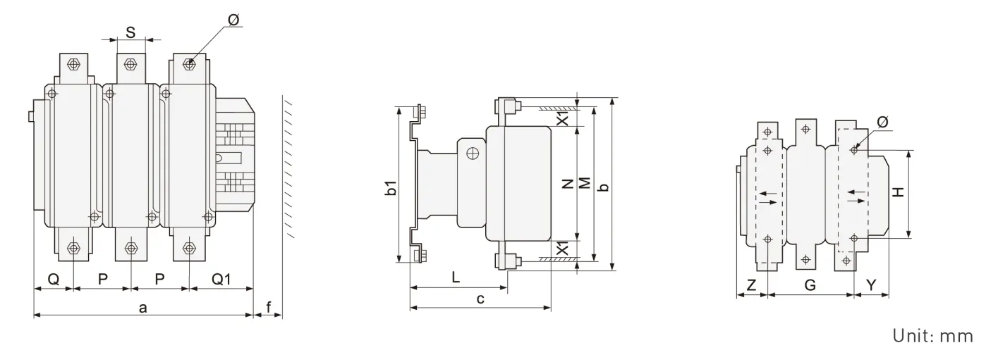
| CQC1 | a | P | Q | Q1 | S | Φ | f | b | b1 | M | N | c | L | G | H | Φ1 | Z | Y | X1 | |
| ≤500V | >500V | |||||||||||||||||||
| 630/800 | 309 | 80 | 60 | 89 | 40 | M12 | 201 | 304 | 280 | 264 | 202 | 255 | 155 | 180(100-195) | 180 | 10.5 | 60.5 | 68.5 | 20 | 30 |
CQC1 Series Accessories
Quick selection table/specification

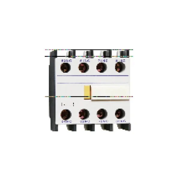
Specification of auxiliary contact [air delay type]
| model | Delay range | Number of delayed contacts | Delay mode | Hook mode |
| S4-20 | 0.1s~3s | مفتوح عادةً + مغلق عادةً | Power on delay | Top hanging |
| S4-22 | 0.1s~30s | |||
| S4-24 | 10s~180s | |||
| S5-20 | 0.1s~3s | Power off delay | ||
| S5-22 | 0.1s~30s | |||
| S5-24 | 10s~180s |
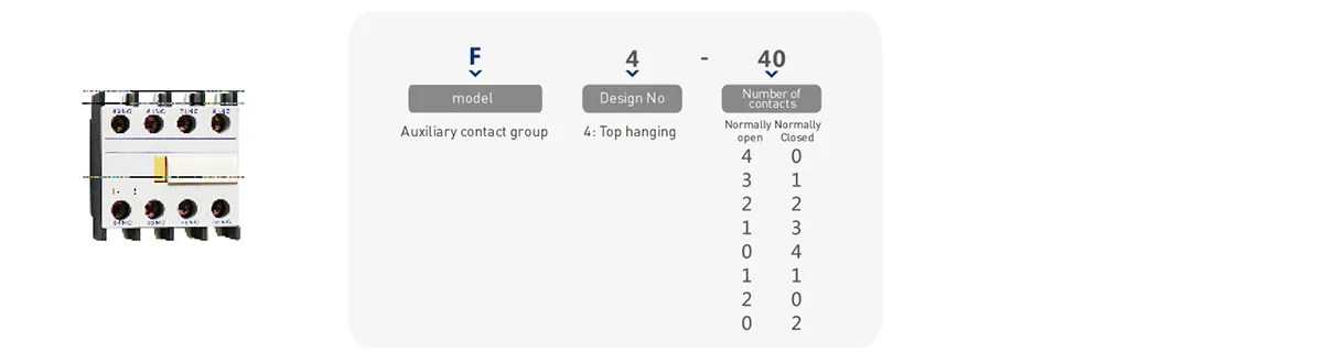
Auxiliary contact specification
| model | Number of contacts | Hook mode | |
| Normally open [NO] | Normally Closed [NC] | ||
| F4-40 | 4 | 0 | C0C1-09~95 series contactors are top mounted CQC1-115-800 series contactors are side mounted |
| F4-31 | 3 | 1 | |
| F4-22 | 2 | 2 | |
| F4-13 | 1 | 3 | |
| F4-04 | 0 | 4 | |
| F4-20 | 2 | 0 | |
| F4-11 | 1 | 1 | |
| F4-02 | 0 | 2 | |
Technical parameters
09~95A performance index
| CQC1-09 | COC1-12 | COC1-18 | COC1-25 | COC1-32 | COC1-40 | COC1-50 | COC1-65 | CQC1-80 | CQC1-95 | |||
| Rated working current le,A(AC-3) | 400V | 9 | 12 | 18 | 25 | 32 | 40 | 50 | 65 | 80 | 95 | |
| 690V | 6.6 | 8.9 | 12 | 18 | 21 | 34 | 39 | 42 | 49 | 49 | ||
| Agreed free air heating current lth (A) | 25 | 25 | 25 | 40 | 40 | 65 | 80 | 80 | 125 | 125 | ||
| Rated working voltage Ue (V) | 380/400、660/690 | |||||||||||
| Rated insulation voltage Ui (V) | 690V | |||||||||||
| AC-3(6le、le) | Electrical life (times) | 200×104 | 200×104 | 200×104 | 200×104 | 200×104 | 200×104 | 200×104 | 200×104 | 200×104 | 200×104 | |
| Frequent operation(h) | 1200 | 1200 | 1200 | 1200 | 600 | 600 | 600 | 600 | 600 | 600 | ||
| AC-4(6le、6le ) | Electrical life (times) | 20×10 | ||||||||||
| Frequent operation(h) | 300 | |||||||||||
| Rated working current le(A) | 380/400V | 3.5 | 5 | 7.7 | 8.5 | 12 | 18.5 | 24 | 28 | 37 | 44 | |
| 660/690V | 1.5 | 2 | 3.8 | 4.4 | 7.5 | 9 | 12 | 14 | 17.3 | 21.3 | ||
| Mechanical life (times) | 1000×104 | 800×104 | 600×104 | |||||||||
| نقاط تلامس مساعدة | Agreed free air heating current lth(A) | 10 | ||||||||||
| Electrical life (times) | AC-15(360VA) | 100×104 | 80×104 | 60×1043 | ||||||||
| DC-13(33W) | ||||||||||||
| Minimum load that can be connected | 24V 10mA | |||||||||||
| ملف | Rated control supply voltage Us (V) | AC(50Hz/60Hz)24、36、110、220、380;DC:24、48、110、220 | ||||||||||
| pull-in voltage | 85%~110%Us | |||||||||||
| Release voltage | 20%~75% US(AC)10%~75% Us(DC) | |||||||||||
| 50Hz AC coil power (VA) | start | 65 | 65 | 65 | 100 | 100 | 200 | 200 | 200 | 200 | 200 | |
| Sorption | 8 | 8 | 8 | 11 | 11 | 20 | 20 | 20 | 20 | 20 | ||
| DC coil power (w) | start | 11 | 11 | 11 | 13 | 13 | 22 | 22 | 22 | 22 | 22 | |
| Sorption | ||||||||||||
| Wiring capacity of termina mm²(min/max) | Non prefabricated end cord | 1 piece | 1/4 | 1.5/6 | 1.5/10 | 2.5/10 | 2.5/25 | 4/50 | ||||
| 2 pieces | 1/4 | 1.5/6 | 1.5/6 | 2.5/10 | 2.5/16 | 4/25 | ||||||
| Flexible wire with prefabricated end | 1 piece | 1/4 | 1/6 | 1/6 | 1/9 | 2.5/25 | 4/50 | |||||
| 2 pieces | 1/2.5 | 1/4 | 1/4 | 1.5/6 | 2.5/10 | 4/16 | ||||||
| Non prefabricated end hard wire | 1 piece | 1/4 | 1.5/6 | 1.5/6 | 1.5/10 | 2.5/25 | 4/50 | |||||
| 2 pieces | 1/4 | 1.5/6 | 1.5/6 | 1.5/10 | 2.5/16 | 4/25 | ||||||
| Tightening torque of main circuit wiring | N·M | 1.7 | 2.5 | 5 | 9 | |||||||
115A-800A performance index
| technical parameter | CQC1-115 | CQC1-150 | CQC1-185 | CQC1-225 | CQC1-265 | CQC1-330 | CQC1-400 | CQC1-500 | CQC1-630 | CQC1-800 | ||
| Rated working current le(A) | AC-3 | 400V | 115 | 150 | 185 | 225 | 265 | 330 | 400 | 500 | 630 | 800 |
| 690V | 86 | 107 | 118 | 135 | 172 | 225 | 305 | 355 | 460 | 485 | ||
| AC-4 | 400V | 52 | 60 | 79 | 85 | 105 | 117 | 138 | 147 | 188 | 242 | |
| 690V | 49 | 57 | 69 | 82 | 98 | 107 | 135 | 145 | 170 | 215 | ||
| Maximum rated power of controllable three-phase squirrel cage motor Pe (k) | AC-3 | 400V | 55 | 75 | 90 | 110 | 132 | 160 | 200 | 250 | 335 | 450 |
| 690V | 80 | 100 | 110 | 129 | 160 | 220 | 280 | 335 | 450 | 475 | ||
| AC-4 | 400V | 25 | 30 | 40 | 45 | 55 | 63 | 75 | 80 | 100 | 129 | |
| 690V | 45 | 51 | 63 | 75 | 90 | 100 | 129 | 140 | 160 | 200 | ||
| Agreed free air heating current lth (A) | 200 | 200 | 280 | 280 | 360 | 360 | 580 | 580 | 850 | 850 | ||
| Rated working voltage Ue (V) | 400、690 | |||||||||||
| Rated insulation voltage Ui (V) | 690 | |||||||||||
| AC-3 | Electrical life (times) | 60×104 | 50×104 | 30×104 | 20×104 | 15×104 | ||||||
| Frequent operation (h) | 600 | 300 | 150 | |||||||||
| AC-4 | Electrical life (times) | 15×104 | 8×10⁴ | 5×10⁴ | 3×10⁴ | |||||||
| Frequent operation (h) | 150 | |||||||||||
| Mechanical life (times) | 300×104 | 100×104 | 60×104 | |||||||||
| نقاط تلامس مساعدة | Agreed free air heating current lth (A) | 10 | ||||||||||
| Electrical life (times) | AC-15(360VA) | 60×104 | 50×104 | 30×104 | 15×104 | |||||||
| DC-13(33W) | ||||||||||||
| Coil parameters | Rated control supply voltage Us (V) | AC50HZ:24、48 110 230(220)240 (double coil energy-saving type(380) | AC50HZ:48、110 230(220)240 (double coil energy-saving type(380) | |||||||||
| pull-in voltage | 85%~110%Us | |||||||||||
| Release voltage | 20%~75%Us | |||||||||||
| coil power (VA) | start | 560 | 800 | 750 | 1000 | 1100 | 1600 | |||||
| Sorption | 45 | 55 | 8 | 12 | 16 | 20 | ||||||
| Pickup time (ms) | 23~35 | 20~35 | 30~65 | 40~75 | 40~80 | 50~100 | ||||||
| Release time (ms) | 5~15 | 7~15 | 100~170 | 100~170 | 100~200 | 130~230 | ||||||
| Main circuit connection capacity | Copper conductor | Number of roots | 1 | 1 | 1 | 1 | 1 | 1 | 2 | 2 | – | |
| Conductor section mm | 120 | 150 | 185 | 240 | 240 | 150 | 240 | – | ||||
| Copper bar | Number of roots | 2 | 2 | 2 | 2 | 2 | 2 | 2 | 2 | 2 | 2 | |
| Dimension mm | 20×3 | 25×3 | 25×3 | 32×4 | 32×4 | 30×5 | 30×5 | 50×5 | 60×5 | 60×5 | ||
| Auxiliary circuit contrd circuit | Flexible cord mm² |
1 | 2.5 | |||||||||
| 2 | ||||||||||||
| Hard wire mm² | 1 | 4 | ||||||||||
| 2 | ||||||||||||
لماذا تختار CHAC
مع خبرة تصنيع تزيد عن 30 عامًا، وأكثر من 1100 موظف، وأكثر من 100 مليون عمود
بفضل طاقتها الإنتاجية السنوية ونظام الإنتاج الآلي 90%، توفر شركة CHAC طاقة إنتاجية مستقرة ومعايير صارمة
مراقبة الجودة لعملاء OEM/ODM العالميين. يدعم نظام التصنيع الداخلي الخاص بنا على المدى الطويل
تعاون مع العلامات التجارية الكهربائية والمستوردين والموزعين.

30+
سنوات الخبرة
متخصص في تصنيع المعدات الكهربائية منخفضة الجهد

1100+
الموظفين
فريق محترف يضمن جودة ثابتة والتسليم

١٠٠ مليون+
السعة السنوية للأعمدة
قدرة إنتاجية واسعة النطاق لتلبية الطلب العالمي

90%
الإنتاج الآلي
الأتمتة المتقدمة لتحقيق كفاءة واتساق عاليين
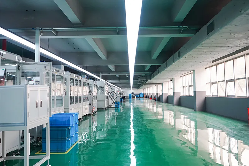
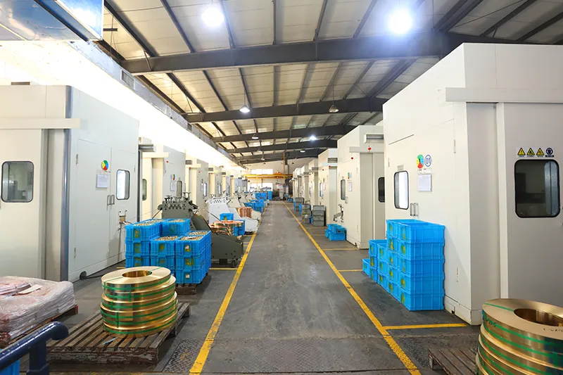
خط التجميع الآلي

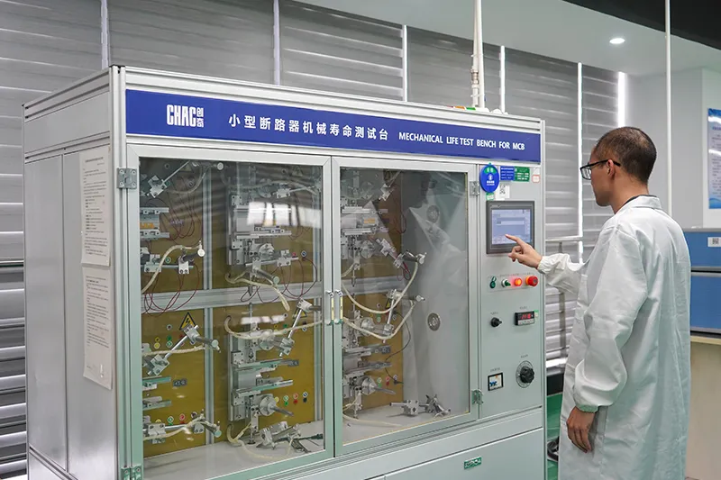
مختبر اختبار
حقن وختم
فحص الجودة



نظام صارم لمراقبة الجودة يضمن أن كل منتج يلبي المعايير العالمية.
ما الذي يمكننا تخصيصه؟
تدعم تشاك تخصيص جهد الملف وتكوين نقاط التلامس المساعدة،,
المعلمات الكهربائية، والعلامة التجارية للمنتج، وتصميم التعبئة والتغليف، والتطوير الهندسي وفقاً لمعدات العملاء ومتطلبات السوق.

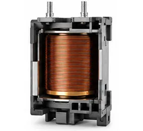
جهد الملف
خيارات جهد ملف التيار المتردد وتيار مستمر مصممة لتناسب متطلبات التطبيق.

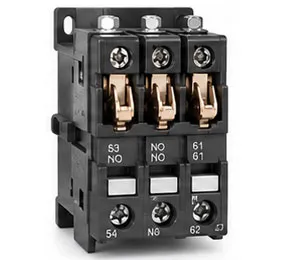
ملامسات مساعدة
مجموعات اتصالات مساعدة مرنة لوظائف تحكم مختلفة.

المعاملات الكهربائية
يمكن تخصيص التصنيفات الحالية، ونطاقات الحماية، والمعلمات الوظيفية.
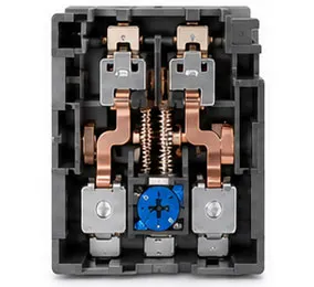

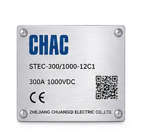
علامة تجارية للمنتج
شعارات الملصقات الخاصة، ولوحات الأسماء، ودعم تعريف المنتج.

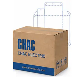
تصميم عبوات
علب مخصصة، وملصقات، وأدلة، وحلول تغليف.

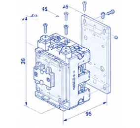
التطوير الهندسي
الدعم من تحسين الرسم إلى تطوير المنتج وتطابق التطبيقات.
CQC1 Product FAQ
What loads can the CQC1 contactor switch?
Use the published utilization category, operational current and voltage for the selected variant. Resistive, motor and capacitive loads require different checks.
How do I select an AC contactor size?
Start with load current, utilization category, starts per hour, coil voltage, poles and short-circuit coordination. Current alone is not enough.
Can a thermal relay be paired with it?
Where the product record supports the combination, a thermal relay can form a motor starter. Confirm mechanical fit, current range and control wiring.
Which coil voltage should I specify?
Match the control supply shown on the project drawing with the coil option for the exact model. Never assume the coil voltage from the main circuit.
What accessories are available?
Auxiliary contacts, timers, interlocks or other accessories depend on the series and variant. Confirm the compatible accessory list before ordering.
How should a contactor be commissioned?
Verify terminal torque, coil voltage, contact sequence, insulation and operating current, then record the test results.
Confirm the Right CQC1 Configuration
Send the exact model, operating conditions, quantity, destination market and required documents. CHAC will review the request against the published product data.