Opening two conductors does not mean both conductors have overcurrent protection. That is the central issue when a purchase specification treats 1P+N and 2P MCBs as interchangeable. The correct arrangement follows the source and load diagram, neutral function, required disconnection and exact product construction, not the available module space. This guide separates switched poles from protected poles, explains when line-to-neutral and line-to-line circuits lead to different requirements, and identifies the product and installation records needed before approval.
The short answer is: In common IEC product notation, a 1P+N device has two linked contacts but normally applies overcurrent protection to one pole, while a 2P MCB commonly protects both poles. Either may disconnect two conductors; they are not therefore electrically identical. IEC 60898-1 defines an MCB product and test framework, but it does not decide every installation. Confirm the device diagram, earthing arrangement, neutral-isolation requirement, fault level and local project rules before specifying one.
What actually changes between 1P+N and 2P?
The essential distinction is protection placement. A typical 1P+N MCB contains one protected phase pole and one switched neutral pole; a linked mechanism opens both. A typical 2P MCB contains two protected poles with linked operation. Because notation varies, confirm the front diagram and datasheet.
Switching and overcurrent protection solve different problems. Opening a conductor provides switching or isolation; a thermal or magnetic release responds to overload or short-circuit current. IEC 60898-1 includes tripping and short-circuit test requirements for AC breakers within its scope. It is a product standard—not a certification or an installation design.
Use the manufacturer’s internal diagram, protected-pole designation and time-current data to identify the pole functions. Qualified commissioning checks can verify installation behavior, but continuity alone does not prove which pole has an overcurrent release or reproduce a product type test.
Why does neutral isolation affect the decision?
On a line-to-neutral circuit, opening phase and neutral can provide a clearer isolated boundary than opening phase alone. This matters if an alternate source, shared wiring or abnormal neutral voltage leaves another path connected. It does not replace the project procedure for isolating every source and stored energy.
The earthing system changes the analysis. Local rules may treat neutral switching differently in TN and TT arrangements, while an IT or phase-to-phase supply may have two live conductors rather than an earthed neutral. IEC 60364-5-53 addresses protection, isolation and switching devices; the adopted national edition and project drawings determine the answer.
Contact sequence may also matter. Some devices close the neutral before—and open it after—the phase. Verify this feature and terminal polarity in the exact datasheet.
How do the switched and protected poles compare?
| Decision factor | 1P+N MCB | 2P MCB |
|---|---|---|
| Common arrangement | One protected phase pole plus one switched neutral pole | Two protected poles with linked operation |
| Conductors disconnected | Normally phase and neutral | Normally both connected conductors |
| Overcurrent sensing | Normally on the phase pole only | Normally on both poles; confirm the diagram |
| Neutral isolation | Provided when installed according to the marked L/N terminals | Can isolate both conductors, subject to product suitability and wiring |
| Module width and panel space | Often offered in compact formats | May require more ways, but construction varies |
| Unit-cost tendency | May use fewer protective elements | May cost more with two protected poles |
| Maintenance risk | Wrong L/N termination can defeat the intended arrangement | Wrong assumptions about common trip can cause rework |
| Total cost | Enclosure changes, rewiring, retesting and approval delays can outweigh device-price differences. | |
Do not assign module count from the label alone. Accessories, busbars, terminal access and clearances affect usable capacity. Verify exact width and spacing on the approved datasheet and enclosure layout.
Which supply arrangements change the pole-selection decision?
| Supply or project condition | Likely direction | Evidence to verify |
|---|---|---|
| Line-to-neutral circuit in a TN system | 1P+N may suit required neutral switching without neutral overcurrent protection | Wiring rules, source earthing, polarity and diagram |
| Line-to-neutral circuit in a TT system | Two-conductor disconnection may be required or preferred; 1P+N or suitable 2P can be considered | Local isolation rules, RCD arrangement and neutral-earth conditions |
| Single-phase phase-to-phase circuit | A suitable 2P arrangement is often considered because neither conductor is a conventional neutral | System diagram, voltage and live-conductor protection |
| Generator, UPS or transfer system | Choice depends on neutral treatment at the transfer point | Source bonding, transfer design and backfeed paths |
| IT or unearthed arrangement | Do not assume a 1P+N label matches the conductors | First-fault strategy, insulation monitoring and local design rules |
| Retrofit with uncertain wiring | Pause selection until conductors and sources are traced | Polarity, continuity, prospective fault current and as-built documentation |
Which standards and model documents govern pole selection?
- IEC 60898-1 covers AC circuit breakers for overcurrent protection in household and similar installations within its scope. Its tripping, temperature-rise and short-circuit tests describe product performance; citing the number is not a third-party certificate.
- IEC 60364-4-43 addresses protection of low-voltage installations against overcurrent, including how conductors and protective devices are coordinated.
- IEC 60364-5-53 addresses devices used for protection, isolation, switching, control and monitoring.
- National rules such as BS 7671 or NFPA 70 may use different terminology and requirements. Applicable editions depend on the destination market, supply arrangement, occupancy, equipment instructions and authority having jurisdiction.
An unsupported conformity claim can delay approval or inspection. Ask for documents identifying the exact model, rating and edition. For the product discussed below, only CCC is confirmed; IEC 60898-1 is the stated product standard, not an IEC certification.
How should buyers specify the correct pole arrangement?
- Draw the source and load conductors. State whether the circuit is line-to-neutral or line-to-line and identify the earthing system.
- Separate the switching decision from the protection decision. Record which conductors must open together and which require overcurrent sensing under the applicable code.
- Check voltage, current, trip curve, breaking capacity and prospective short-circuit current under IEC 60364-4-43 or the applicable local rules.
- Verify module width, terminals, busbar compatibility, neutral contact sequence and clearance from current documents.
- Put the destination market, standard edition, evidence package and inspection criteria in the purchase specification.
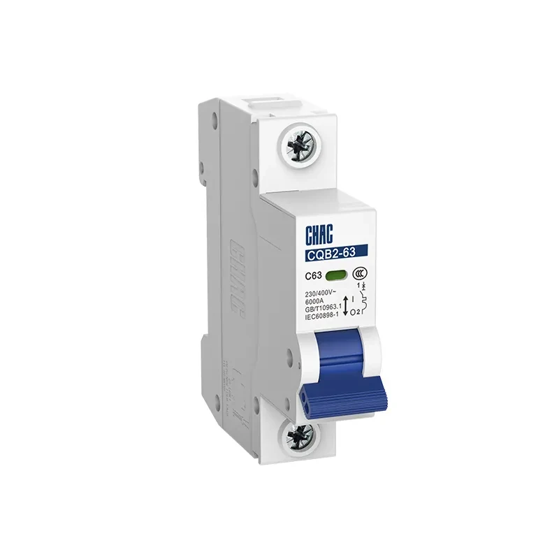
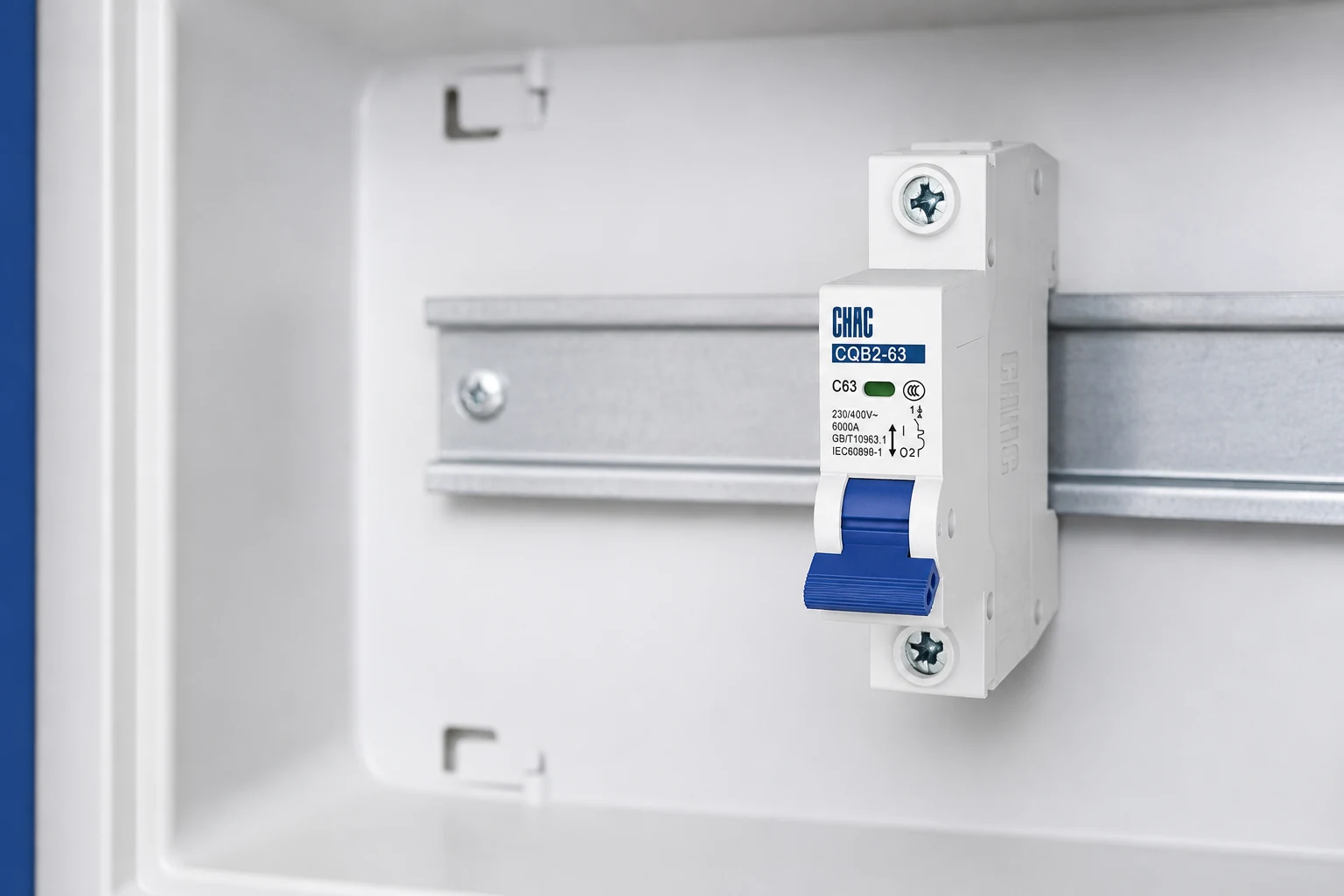
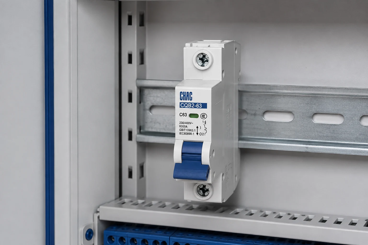
CHAC Electric’s CQB2-63 miniature circuit breaker page lists 1P+N and 2P configurations and confirms CCC. Review its 1P+N vs 2P MCB pole guidance and the broader MCB selection guide before requesting documents.
What must the device diagram show before a pole configuration is approved?
The difference between a 1P vs 2P breaker or a compact 1P+N device depends on what each pole switches and protects in the exact product. Two conductors can be opened together while overcurrent protection is applied to only one; the front width does not reveal that function.
| Selection question | Why it matters | Evidence to request |
|---|---|---|
| Which poles are overcurrent-protected? | Protection and switching may not apply identically to phase and neutral. | Internal diagram and product marking. |
| Is the neutral required to open? | Earthing system, maintenance isolation and local rules determine the need. | Single-line diagram and installation standard. |
| Is two-pole common trip required? | Two linked handles are not automatically an internal common-trip mechanism. | Manufacturer designation and panel approval. |
neutral switching should be specified as a function, not assumed from “N” in a model name. Confirm whether the neutral pole is protected, switched, delayed or solidly connected in the intended arrangement. For an IEC-style product review, the CQB2-63 pole-configuration guidance gives the product context, while the final choice still follows the system diagram and local requirements.
A documented 1P+N MCB can be appropriate for a single-phase circuit when its terminal arrangement, fault rating, isolation function and panel fit are confirmed. It should not be selected only to save module space, and it should not be substituted for a 2P device when both poles require overcurrent protection or a specific common-trip arrangement.
Can a switched neutral pole be used for a second hot conductor?
Do not assume it can. In a phase-to-phase circuit, the second conductor is not a conventional neutral. If protection is required on both ungrounded conductors, a pole intended only to switch N does not establish that function. The device must have the appropriate protected-pole construction, voltage rating and approved application. The same caution applies when comparing an IEC 1P+N device with a US two-pole breaker: the labels do not make them universal replacements.
Neutral, protective earth and PEN must also remain distinct. Schneider Electric’s earthing-scheme definitions identify N/PE separation and the combined protective and neutral function of PEN. A pole marked N is not permission to switch a protective conductor or combined PEN. Establish the conductor roles from the installation design before applying a device diagram.
For a purchase record, write the functions explicitly: number of switched poles, number of overcurrent-protected poles, required linked operation, neutral contact sequence where specified, terminal identification and isolation suitability. Then add the system voltage, fault duty and destination requirements. This is more precise than requesting a narrow case or two handles, and helps prevent a later substitution that preserves appearance but changes protection.
Frequently asked questions
What is the difference between a 1P and 2P circuit breaker?
A 1P device normally provides one protected pole, while a 2P device commonly protects two poles. The actual switching and neutral function must be confirmed from the exact product diagram and the system architecture.
Why does neutral switching matter?
Neutral isolation can affect maintenance safety, polarity, residual-current sensing and the installation rules for the earthing system. It must be selected from the project diagram, not from space-saving goals alone.
Is a 1P+N MCB the same as a 2P MCB?
No. Both may open two conductors, but 1P+N commonly protects one pole and switches neutral; 2P commonly protects both. Confirm the diagram because constructions vary.
Does a 1P+N MCB protect the neutral from overcurrent?
Normally, the N pole is switched but not overcurrent-protected. The phase pole provides that function and linked operation opens neutral; check markings and product data.
Should the neutral always be disconnected in a single-phase circuit?
No universal rule applies. The answer depends on local code, the TN, TT or IT arrangement, the isolation objective and any alternate source.
Can I choose 1P+N simply to save panel space?
Panel space cannot override protection and isolation requirements. Compare datasheet width, clearances, busbars and terminal access; 1P+N devices do not all occupy the same space.
Which option is better for a generator or UPS circuit?
It depends on neutral treatment and how transfer equipment controls bonding and backfeed. Review the single-line diagram and source instructions before choosing.
Can a 1P+N breaker be used to protect two hot conductors?
Not by assumption. A typical N pole is switched without its own overcurrent release. The exact device construction and installation rules must support the protection and disconnection required for both conductors.
Can the N pole be used to switch protective earth or PEN?
No. Neutral switching is not permission to interrupt a protective conductor or a combined protective-earth-and-neutral path. Identify conductor functions and follow the applicable earthing and isolation rules.
References
- Schneider Electric: Definition of standardised earthing schemes; N, PE and PEN relationships, updated August 5, 2026.
- Schneider Electric: Fundamental characteristics of a circuit-breaker; protection, voltage and isolation are separate checks.
- UL Solutions: Panelboard Application Guide; US panel-system markings and approved combinations, not blanket IEC substitution permission.
The right pole label is the result of a documented circuit decision, not a shortcut for making a breaker fit.
If your project drawings define the supply, earthing arrangement, required disconnection, rated current, fault level and destination market, contact CHAC Electric to confirm the appropriate CQB2-63 configuration and supporting documentation.