Part 1. What Does an MCB Symbol Tell You on a Single-Line Diagram?
An MCB symbol on a single-line diagram marks the place where a miniature circuit breaker protects or isolates part of the represented circuit. It is a fast way to understand system arrangement, not a substitute for the project’s wiring drawings, device schedule, or approval records.
That distinction matters when a panel drawing arrives without its full document pack. A single-line sheet usually compresses a complex installation into one path per circuit. It helps a reviewer follow the power path and identify major devices, but it deliberately leaves out many details that would be needed to build, test, or approve the panel.
Start with the purpose of the sheet. Is it a concept diagram, a tender drawing, a coordination drawing, or an issued-for-construction package? The same breaker mark can appear in each, while the amount of information that may safely be inferred from it changes substantially.
Important: Do not approve an MCB model, rating, trip characteristic, or certification claim from a generic drawing mark. Those decisions require the applicable project documents and product evidence.
Part 2. Read the Breaker Mark With Its Tag and the Drawing Legend
A mark becomes useful only when it is read with the text around it. Look for the device tag, circuit reference, panel name, and any legend that explains the drawing convention. A tag such as QF1, CB-12, or a project-specific identifier is usually more useful to procurement and commissioning teams than trying to recognise a shape in isolation.
Use this order when reviewing a sheet:
- Find the device tag next to the breaker mark.
- Trace the upstream and downstream circuit references.
- Locate the project legend or symbol schedule.
- Check whether a separate equipment schedule names the required device attributes.
- Record every item that is still assumed rather than documented.
The question “What is the standard symbol for a circuit breaker?” appears in search results because readers expect one visual answer. In real project work, the safer answer is: use the project legend first. Symbol libraries are valuable references, but they do not replace the convention selected for a particular drawing set.
How Do You Identify Pole Count in an MCB Symbol?
Google results commonly separate searches for a 1-pole MCB symbol, a 2-pole MCB symbol, and a 4-pole MCB symbol. In a single-line drawing, repeated breaker elements or linked switching marks can be a clue that the device has more than one pole, but the visual clue is not a product specification. The drawing legend and device schedule must confirm whether the mark represents 1P, 1P+N, 2P, 3P, or 4P equipment and which poles are protected or switched.
| What you can inspect on the sheet | What must still be verified |
|---|---|
| Number of linked breaker marks or switching paths | Declared pole configuration and whether the neutral is protected or only switched |
| Phase or circuit labels beside the device tag | System arrangement, supply type, and the project’s naming convention |
| Device schedule reference next to the symbol | Rated current, curve, breaking capacity, and approved model |
This is why a search image can help someone recognise a drawing pattern but cannot justify substituting a single-pole device for a multi-pole device. Confirm the pole arrangement against the schedule before procurement or wiring.
Part 3. What Does the Line on Each Side of the Mark Represent?
The line around a breaker mark represents the circuit path at the level of abstraction chosen by the drawing. It can help you see where a branch leaves a busbar, where a feeder continues, or which downstream load group is associated with a protective device. It does not, by itself, show every conductor, terminal, control wire, or physical route.
This is why “line and load” questions need a document-based answer. Read the direction of the system from the source, busbar, or upstream reference toward the labelled load or downstream board. Then confirm that interpretation against the sheet title, cross-references, and legend instead of relying on page orientation alone.
For a panel-builder handover, separate these two notes:
| The single-line sheet can help identify | You still need another document to confirm |
|---|---|
| circuit position and circuit relationship | conductor/terminal detail |
| device tag and panel reference | actual wiring route |
| upstream/downstream context | product rating and trip data |
| likely downstream load group | approved standard and acceptance requirement |
That separation prevents a common review mistake: treating a readable drawing as a complete selection specification.
How Do You Read an MCB Single-Line Diagram?
The related search question “What is a 1 line electrical drawing?” points to a practical need: readers want a repeatable way to follow power flow. A one-line diagram is a simplified representation in which one line stands for a circuit path or group of conductors. It is useful for system relationships and protection-device locations, while detailed wiring, terminal, and installation information remains in other drawings.
- Identify the source, busbar, or upstream board and note the drawing revision.
- Follow the line to the MCB mark and record its device tag.
- Read the downstream label, feeder reference, or load description.
- Open the legend and equipment schedule before interpreting pole count or device type.
- Cross-check ratings, trip curve, interrupting performance, and accessories against manufacturer documentation.
If the sheet does not show a legend, schedule, or clear upstream/downstream reference, mark the item as unresolved instead of filling the gap from a generic symbol chart.
Part 4. How Should You Handle IEC, ANSI, and Symbol-Library Differences?
Searchers commonly ask whether IEC and ANSI circuit-breaker symbols differ, which IEC standard covers graphical symbols, and where they can download a usable library. Treat those questions as a signal to verify the drawing convention, not as a reason to copy a symbol from an unrelated online image.
The IEC graphics and figures guidance points designers to IEC 60617 for graphical symbols and IEC 61082-1 for the preparation of electrotechnical diagrams. Those references explain why a symbol library is useful, but they do not remove the need to read the project legend and revision. A customer drawing may use an approved company library or a local convention that must be followed for that document set.
The Siemens Capital X circuit-breaker library and its single-line symbol library show why a library is useful: it gives designers a controlled vocabulary for diagrams. The project team still needs to identify which convention, revision, and legend apply to the issued drawing.
When a customer sends a PDF, ask four narrow questions before redrawing or quoting from it:
- Is there a project legend or CAD symbol schedule?
- Which drawing revision is being reviewed?
- Which standard or customer convention governs the symbols?
- Does the device schedule define the required electrical and compliance attributes?
This approach is more reliable than declaring that one symbol shape is always right or that a different-looking mark automatically means a different product.
Part 5. When Is an MCB Symbol Not Enough for Selection?
The symbol is not enough when the decision affects a product specification, project acceptance, or safety responsibility. At that point, the reviewer needs the device schedule, system conditions, applicable standard, and the manufacturer documentation for the candidate product.
For example, a diagram may establish that a branch requires a protective device, but it cannot by itself confirm the current rating, poles, interrupting performance, curve, accessories, enclosure context, or certification scope. Those fields belong in a controlled selection record, not in an assumption beside a graphic mark.
Readers who need to move from document interpretation to a product discussion can review the CHAC Electric MCB product range. The correct next step is still to match a documented requirement to the relevant product data; the diagram symbol is only the starting point.
For related reading, use MCB nameplate information when the task is to interpret a device label, and single-pole and double-pole MCB choices when the project documentation has already defined the switching question.
Part 6. What Should You Send for a Technical Review?
A useful technical-support request is a marked-up document package, not only a cropped symbol screenshot. Include the single-line page and its revision, the legend or symbol schedule, the panel or circuit reference, the system conditions supplied by the project, and the applicable customer or project standard.
That information lets the conversation move from “What does this icon look like?” to “What is this circuit required to do, and which documented device evidence is needed?” It also makes it easier to spot a missing schedule before a quotation or panel build proceeds.
If you need that review, send the document set to CHAC Electric Technical Support. For broader product-family context, the terminal electrical devices category shows where MCBs sit within the site’s low-voltage terminal-device range.
Product recommendation
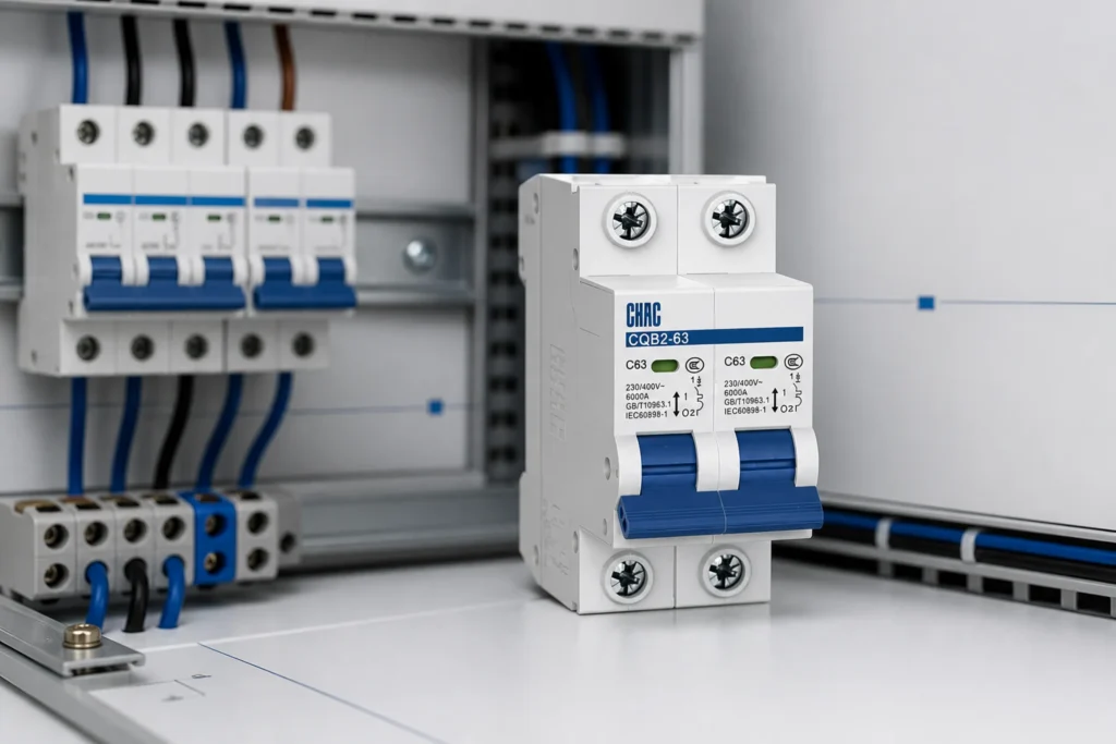
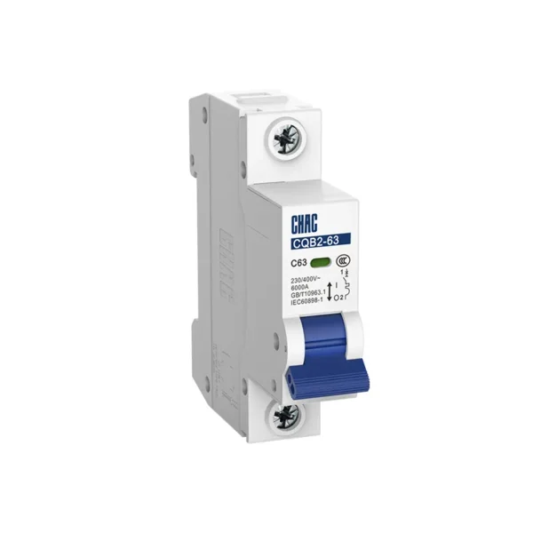
CQB2-63 Miniature Circuit Breaker For Power Systems | CHAC Electric
How should an MCB symbol be read with the schedule?
MCB symbols communicate a device role on a drawing, but the symbol alone does not establish the breaker’s poles, curve, breaking capacity or approval scope. Read it with the legend, circuit schedule, conductor arrangement and revision-controlled device data. A single-line diagram compresses the circuit; it does not replace the detailed wiring diagram.
| Drawing item | Question to answer | What still needs product evidence? |
|---|---|---|
| Symbol and legend | What device role is represented? | Exact model and standard scope |
| Pole notation | Which conductors are switched or protected? | Protected-pole and terminal arrangement |
| Schedule fields | What current, curve and fault duty are required? | Marked ratings and technical documents |
Use the circuit breaker symbol as the start of a drawing review, then verify the selected product. The CQB2-63 MCB page can support the product-data step, while the project legend controls how the symbol is interpreted.
Does an MCB symbol show the breaker’s trip curve?
Usually not by itself. Confirm the curve in the circuit schedule and selected model markings or datasheet.
Can a single-line symbol replace a wiring diagram?
No. It summarizes the power circuit. Terminal wiring, control interfaces, neutral routing and accessory connections require the applicable detailed drawings.
FAQs
What is the standard symbol for a circuit breaker?
Use the legend and convention specified for the project drawing. Public symbol libraries are useful references, but they do not override the controlled legend in an issued document set.
Can I identify an MCB model from a single-line symbol?
No. A symbol may identify a protective-device position and circuit relationship, but model identification needs the device schedule and manufacturer documentation.
What does the line and load information around an MCB mean?
Read it as part of the represented circuit path, then confirm the source, downstream reference, and load description from the drawing labels and cross-references. Do not treat a single-line sheet as detailed wiring instructions.
Are IEC and ANSI circuit-breaker symbols always the same?
Do not assume they are interchangeable. Confirm the convention required by the project or customer and use its legend or approved symbol library.
Where can I find a circuit-breaker symbol library?
Use a controlled library that matches the project’s drawing environment. The Siemens Capital X circuit-breaker and single-line libraries are examples of public reference libraries; the project legend remains the final context.
What should a panel builder check before selecting an MCB?
Obtain the approved device schedule, system conditions, required standard, and product evidence. A diagram symbol alone does not establish those selection inputs.
What is a one-line electrical drawing used for?
A one-line electrical drawing gives a simplified view of sources, feeders, protective devices, and load relationships. It supports design review and coordination, but detailed wiring and terminal work require the relevant schematics, schedules, and installation drawings.
What does an MCB look like on a diagram?
The mark varies with the drawing library and project convention. Look for the breaker mark together with its device tag, connected circuit line, and legend entry rather than relying on an isolated image.
How can I tell whether an MCB symbol represents one pole or several?
Use the linked marks, phase labels, and device tag as clues, then confirm the declared pole configuration in the legend or equipment schedule. The symbol alone cannot confirm whether a neutral is protected or only switched.
What is the symbol for a single-phase circuit?
There is no safe universal shortcut based only on page orientation or one line. Confirm the phase and neutral arrangement from the project legend, supply description, and circuit schedule before selecting an MCB.
References
- IEC: Graphics and figures for electrotechnical diagrams
- U.S. Nuclear Regulatory Commission: Typical Electrical Drawing Symbols and Conventions
- Control.com: Single-line electrical diagrams
- Siemens Capital X: Circuit Breaker Symbol library
- Siemens Capital X: Single Line Electrical Symbols library
- JLCPCB: Circuit Breaker Symbols — IEC, ANSI & How to Read
- IEC 60617 graphical symbols database
- IEC 60947-2 circuit-breakers