A distribution board can have the right current ratings and still be specified against the wrong earthing arrangement. The important distinction is not merely how many conductors enter the enclosure, but where neutral and protective functions are combined, separated and connected to earth. That arrangement affects the fault path, residual-current protection and maintenance isolation. This guide compares TN-C, TN-S, TN-C-S, TT and IT systems, then explains what drawings and commissioning records must establish before a board is approved.
The short answer is: TN-C power supply system, TN-S, TN-C-S, TT, and IT arrangements define the source-to-earth relationship and the return path for fault current. Under IEC 60364, a 30 mA RCD can provide additional protection in specified applications, but it cannot correct an open PEN conductor or an improper neutral-earth bond. Confirm the system, transition point, backup-source behavior, device type, and verification plan before approving a board.

These designations commonly appear in 230/400 V building and industrial distribution, but they describe earthing architecture rather than voltage alone. The first letter identifies the source relationship to earth; the second identifies how exposed conductive parts are connected. Additional letters show whether neutral and protective functions are combined or separated.
How does each earthing arrangement change the fault path?
The key question is how current returns to the source after a live conductor touches exposed metal. In TN systems, a metallic protective path normally supports automatic disconnection. TN-C uses one PEN conductor for neutral and protective functions; TN-S keeps N and PE separate; TN-C-S uses a PEN upstream and separates the functions at a defined transition.
TT returns fault current through installation and source electrodes, often making the loop too resistive for overcurrent protection alone. IT isolates the source from earth or uses a high impedance; a first insulation fault may raise an alarm, but a second fault must be cleared.
| System | Neutral and earth arrangement | Typical protection implication | What buyers should verify first |
|---|---|---|---|
| TN-C | N and PE combined as PEN | No RCD in the TN-C section | PEN route, continuity, size, and transition |
| TN-S | N and PE separate throughout | Automatic disconnection verified by loop tests | PE continuity, loop values, and bonding |
| TN-C-S | PEN upstream; N and PE downstream | Protection depends on a permanent split | No downstream re-bonding and correct RCD placement |
| TT | Local installation electrode | RCDs commonly provide disconnection | Electrode resistance and RCD performance |
| IT | Source isolated or impedance-earthed | First fault may alarm | Insulation monitoring and second-fault response |
IEC 60364-6 requires appropriate inspection and testing. TN needs protective-conductor and loop verification; TT needs electrode and RCD checks; IT needs insulation monitoring and a first-fault response.
Why do PEN continuity and the transition point matter?
Most TN-C system risk centers on the PEN conductor. If the PEN becomes loose or open, load current can shift exposed metal connected to it toward line-to-neutral voltage, especially with unbalanced single-phase loads on a three-phase supply. An ordinary RCD downstream is not a dependable remedy for this upstream failure because current leaving and returning through the monitored live conductors can remain balanced.
The TN-C to TN-S transition is the point where the PEN terminates and separate neutral and protective-earth conductors begin. After that split, N and PE must remain separate downstream; reconnecting them can place normal load current on protective conductors, create parallel return paths, and cause unwanted RCD operation. This is why the TN-C-S distribution box layout must show distinct bars, their bonding arrangement, and the exact PEN termination.
IEC 60364-5-54 gives conductor and bonding requirements, including minimum PEN cross-sections in the conditions covered by the standard; local rules and the utility connection agreement still govern the final design. Procurement documents should therefore identify the conductor material and size, termination method, mechanical protection, inspection access, and ownership of the transition point.
How should protection selection follow the earthing system?
Protection selection starts with the fault-current path. In TN-S and separated TN-C-S, loop impedance determines whether an overcurrent device can disconnect in time. For TT, assess the installation electrode, residual-current arrangement and required disconnection performance under the applicable national rules. A generic resistance calculation is not an electrode acceptance target or evidence that the complete installation is safe.
RCDs compare current in monitored live conductors; they do not provide overload protection unless combined with it, nor detect every hazard. RCCB versus RCBO, residual rating, delay, and current type must reflect coordination, leakage, and load electronics. RCBO selection belongs in the system study, not a late substitution. See the related guide to RCD wiring and electrical safety standards.
| Project condition | Main protection focus | Useful verification method | Commercial risk if ignored |
|---|---|---|---|
| TN-S commercial board | Loop impedance and coordination | PE continuity and loop test | Incorrect trip performance |
| TN-C-S with RCD groups | N/PE separation and RCD type | Inspection and instrumented RCD test | Nuisance trips or blind spots |
| TT with outdoor loads | Electrode and residual protection | Electrode resistance and RCD trip-time tests | Failure to disconnect |
| IT continuity-critical process | Monitoring and second-fault control | Monitor test and alarm response | Undetected first fault |
| Utility plus island sources | Neutral reference in every mode | Transfer and island-mode tests | Redesign or failed disconnection |
Name each test in the specification: protective-conductor continuity, insulation resistance, loop impedance, electrode resistance, polarity, and instrumented RCD operation as applicable. An RCD test button checks its mechanism but not the external PE or electrode. See the guide to commercial building ground resistance.
Protection schedules cannot simply be copied. Each system changes loop impedance, neutral switching, RCD use, first-fault behavior, and verification. Coordinate ratings with actual prospective fault current and local rules.
What must drawings show for every source mode?
Drawings should state the earthing system, voltage, frequency, source type, N-PE separation point, protection logic, and code edition. IEC 60364 covers installation design and verification; IEC 61008-1 and IEC 61009-1 define RCD device categories, not blanket certification of an installation.
A generator may form a new neutral reference through its winding, bonding, and transfer arrangement. A battery inverter may also create a local reference in island mode. State whether neutral is switched, where each source bond exists, how disconnection works, and which RCD type the source manufacturer requires.
On the single-line diagram, mark every source mode, the TN-C-S split or TT electrode, and separate N and PE bars. Specify prospective fault current, disconnection criteria, and IEC 60364-6 records. Review protection whenever utility and island modes differ.
The durable principle is straightforward: before comparing device ratings, make sure everyone is evaluating the same source, neutral reference, and fault path.
What changes when a generator or inverter becomes the source?
The utility-mode earthing label is not enough to approve backup operation. Record the source-to-earth connection, neutral treatment, transfer arrangement and protective path in each operating mode. A generator or inverter may have different fault-current behavior from the utility, so the designer must establish how the selected protection disconnects in that mode. Do not assume a circuit that passes a utility-fed check also passes on an islanded supply.
Schneider Electric’s definition of standardised earthing schemes explains the source and conductor relationships. It also warns against recreating a TN-C section downstream of a separated TN-S arrangement. That distinction matters when an old drawing is reused: a conductor marked N is not automatically a PEN, and a protective conductor must not be treated as a normal load-return path.
Ask the commissioning team for a mode-by-mode record rather than a single pass/fail statement. It should identify the active source, transfer state, neutral reference, protective-device arrangement and applicable verification results. Where IT continuity is intended, the first-fault response and second-fault disconnection strategy need their own documented design. An earthing label alone proves neither.
Power supply systems questions
What is the difference between TN-C and TN-C-S?
TN-C uses one PEN conductor for neutral and protective functions throughout the relevant section. TN-C-S combines those functions upstream and separates them at a defined point; after the split, neutral and PE must remain separate.
Can an RCD be used on a TN-C system?
Not in the TN-C section where normal return current and protective current share one PEN conductor. An RCD may be applied only after a valid transition to separate neutral and PE, and it still does not protect against every consequence of an upstream PEN failure.
Why is TT commonly paired with RCD protection?
In TT systems, the local earth electrode may not provide enough fault current for an overcurrent device alone to disconnect reliably. That makes residual current protection a common and often essential measure, supported by electrode resistance testing and disconnection calculations.
Is IT always safer than TN-S?
No. IT can support continuity because the first insulation fault may produce an alarm rather than immediate shutdown. It requires insulation monitoring, trained fault response, and protection that clears a second fault under the actual conductor arrangement.
What should appear on export documents for a low-voltage panel?
Identify the system, voltage, source arrangement, standards, conductor separation, prospective fault level, and tests. If a generator, UPS, or battery inverter changes the neutral reference, show every mode on the single-line diagram and commissioning record.
Does the earthing arrangement stay the same during backup operation?
Not necessarily. Source bonding, neutral switching and transfer equipment can change the arrangement. The designer must document protection and isolation for utility, generator and inverter modes separately.
For a related selection reference, see Power supply systems explained tnc.
Continue with this related guide: Voltage Protector Keeps Tripping How.
Power supply systems references
- Schneider Electric: Definition of standardised earthing schemes; updated August 5, 2026. Definitions do not by themselves establish project-specific protection settings.
- Schneider Electric: Form factors of RCDs; distinguishes residual-current device arrangements and their protection functions.
- IET: BS 7671 Requirements for Electrical Installations; national implementation must be checked against the applicable edition and project jurisdiction.
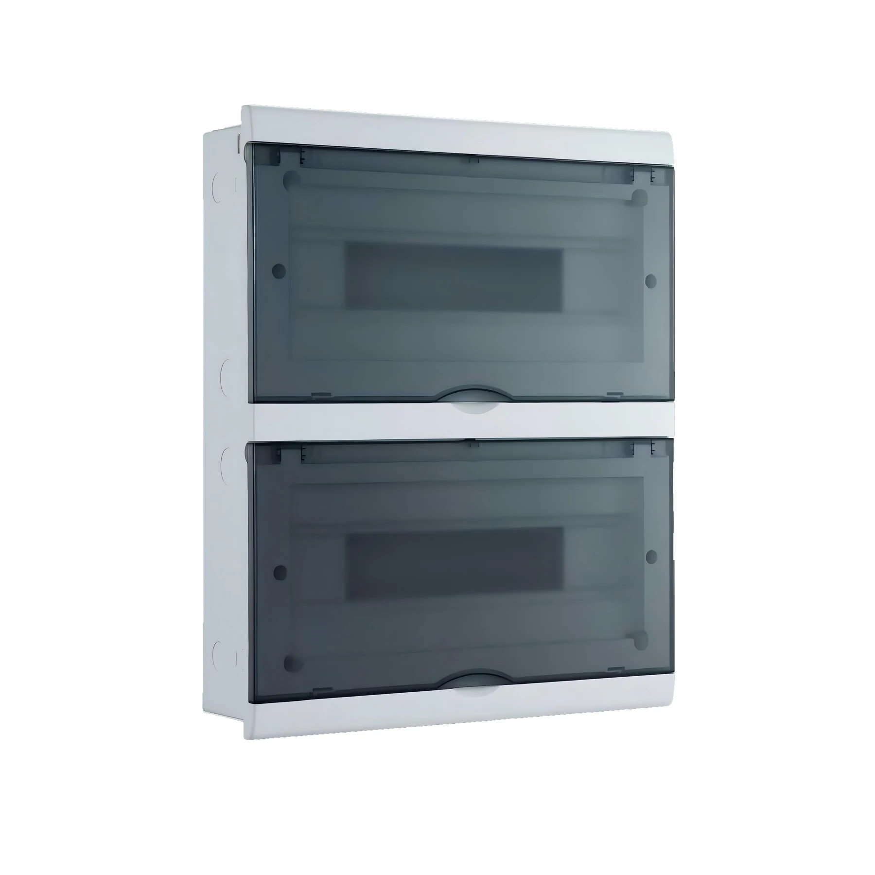
For teams finalizing low-voltage distribution packages, The CQMG20B distribution box is an enclosure reference for a documented layout review; its product name does not establish suitability for every earthing system. Contact CHAC Electric to review the intended system and sourcing record; final suitability still depends on the actual power supply system, destination rules, source modes, and verified test records.