
A list of DC contactor manufacturers is useful only when it separates the switching duties being compared. A supplier of industrial DC motor contactors, a maker of sealed battery contactors and a producer of board-mounted DC cutoff relays may all appear in the same search, yet their products are not drop-in alternatives. Matching coil voltage or a headline current figure can conceal a different load-breaking limit, mounting arrangement or control sequence. This guide identifies ten manufacturers or supplier portfolios with official public product information, explains where their documented offerings differ, and gives buyers a method for turning the list into a shortlist for a particular system.
The short answer is to compare DC contactor manufacturers by exact switching duty and evidence, rather than assign a universal winner. The ten-entry shortlist below covers battery/charging, industrial switching and adjacent DC relay applications. Carrying current, load-breaking current and short-circuit withstand are separate ratings; a large value for one does not establish the others. Require a model-specific datasheet, control specification and protection-coordination review before comparing quotations. This article is published by CHAC, one of the listed suppliers. Its commercial interest is disclosed, and inclusion or table position is not an independent performance ranking.
How were these ten manufacturers selected?
The selection criterion was an accessible official product portfolio relevant to DC switching, checked on 20 October 2026. The comparison records product scope and an application-review question. It does not score market share, independently tested reliability, customer satisfaction or price, because comparable evidence was not collected. The numbers identify entries; they are not rank positions.
The supplier table links directly to the primary sources for each entry. “Price positioning” is recorded as not established where no like-for-like quotation was obtained. A current catalogue also needs lifecycle review: Panasonic’s DC cutoff-relay page, for example, labels EP Relays “Not Recommended for New Design” and shows partial discontinuation. A product appearing in search results is not by itself a sound choice for a new platform.
Which ten DC switching manufacturers should buyers investigate?
| Entry and official source | Documented product focus | Relevant buyer or application | Price positioning |
|---|---|---|---|
| 1. TE Connectivity | DC contactor portfolio including KILOVAC and AMP+ high-voltage products | Vehicle and industrial buyers checking a specific contactor’s carrying and interruption duties | Not established; request a model-specific quote |
| 2. Sensata Technologies / GIGAVAC | Sealed automotive and industrial contactors, with separately identified pre-charge products | Battery, charging and industrial system teams comparing main and pre-charge roles | Not established; request a model-specific quote |
| 3. Albright International | DC contactors, motor-reversing products and emergency disconnects; low- and high-voltage families | DC motor and equipment designers matching the correct product family and duty | Not established; request a model-specific quote |
| 4. Schaltbau | AC/DC contactors with application information for rail, energy, industry and e-mobility | System designers reviewing DC arc interruption and application-specific switching | Not established; request a model-specific quote |
| 5. Panasonic Industry | High-capacity DC cutoff relays; the page distinguishes EP and HE-V series | PCB/equipment designers evaluating DC relay applications; not an automatic substitute for a main battery contactor | Not established; confirm lifecycle status before quotation |
| 6. TDK | HVC high-voltage contactors for DC charging, storage and battery disconnect units | Battery-system teams checking carrying, cut-off, withstand and feedback functions separately | Not established; request a model-specific quote |
| 7. Littelfuse | High-voltage DC contactor relays with polarized/non-polarized and coil-economizer options | Vehicle, charging and industrial buyers comparing required contact and coil configurations | Not established; request a model-specific quote |
| 8. Eaton | Industrial DC contactors, including separately described reversing and interruption duties | Industrial equipment teams; verify load-breaking capability instead of assuming every reverser can break load | Not established; request a model-specific quote |
| 9. ABB | GF, GAF and GA DC switching contactors with application-specific utilization ratings | PV, charging, UPS and storage designers matching the declared category and wiring | Not established; request a model-specific quote |
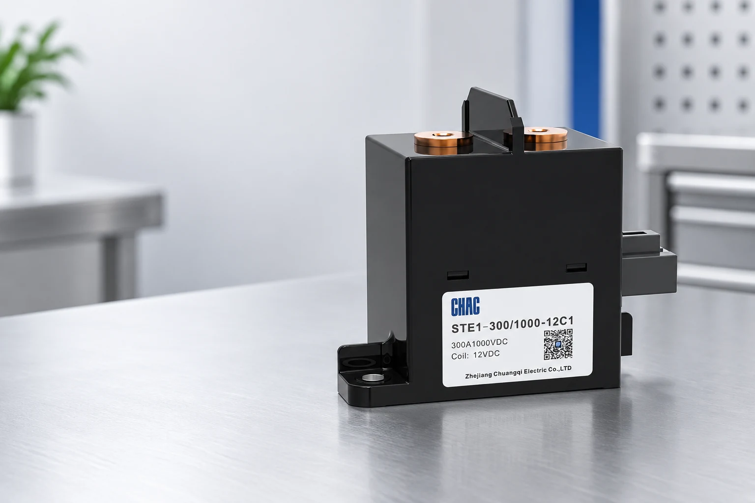
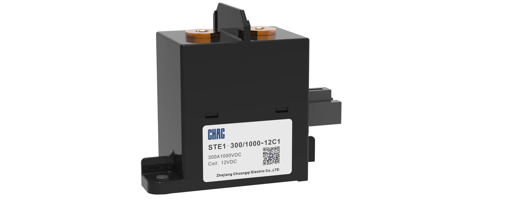
| 10. CHAC Electric | STE1, STE2 and STE3 high-voltage DC contactor families listed in the public category | OEM and panel buyers requesting exact model data, samples and destination-market documents | Not established; request a configuration-specific quote |
These product classes overlap in the broad act of DC switching, but they differ in current path, construction, installation and intended system role. Narrow the application first. Comparing a board-mounted relay with an industrial open-frame device or sealed battery contactor on price alone hides the engineering needed to make the substitution work.
Which ratings must be compared on the same basis?
A high-voltage DC contactor can carry one current continuously, interrupt a different current at a stated voltage, and withstand a short-circuit pulse only for a limited time. The figures must stay attached to their conditions. TE’s public portfolio, for example, describes an AMP+ 500–500L product with 500A continuous carrying capability and a 2,000A interruption statement at 320V DC. That does not establish 2,000A interruption at its separately stated 900V DC capability.
TDK provides another useful distinction: its HVC45 description states a short-circuit current handling capability of 12kA for 5ms and separately gives cut-off values of 900A at 1,000V DC and 2,200A at 450V DC. A 12kA withstand pulse is therefore not a 12kA breaking claim. These examples explain datasheet interpretation; they do not compare the two manufacturers under equal test conditions.
| Requirement | Required conditions | Decision it supports |
|---|---|---|
| Continuous current | Ambient, cable/busbar arrangement, duty and permitted temperature rise | Thermal suitability in the actual enclosure |
| Making and load-breaking duty | Voltage, current, load characteristics, polarity and operation count | Permitted switching, including abnormal operating states |
| Short-circuit withstand and protection | Pulse current, duration and the specified protective arrangement | Coordination with the fuse or other protective device |
| Coil and feedback | Pickup/hold requirements, suppression, economizer and auxiliary-contact behavior | Control compatibility and diagnostic strategy |
| Electrical endurance | Load voltage/current, cycle timing and acceptance criteria | A defensible comparison of service duty |
The same discipline applies to catalogue “bidirectional” claims. Confirm both permitted current flow and the relevant interruption duty, including reversal during charging or regeneration. Eaton’s industrial page explicitly distinguishes a non-load-break reverser from other products with bidirectional interrupting capability. One family’s description cannot be transferred to every product carrying the same company name.
How do pre-charge and coil control change the shortlist?
A capacitive DC link can draw substantial inrush when connected to a source. Where the approved system uses a precharge contactor, evaluate its resistor path, charging interval, repetition rate and the conditions for closing the main contactor. The main switch and the pre-charge switch do not necessarily perform the same duty. Sensata lists a separate P-series pre-charge family, illustrating why these roles should be specified independently.
Match the coil control to the controller’s supply and output capability. Pickup current, holding power, suppression and economizer behavior can affect timing and heat. Do not assume a 12V coil can be driven by any 12V controller output, or add an external suppression component without checking the manufacturer’s control instructions.
Auxiliary feedback also needs interpretation. An ordinary auxiliary indication is not automatically a certified mirror-contact function or proof that the high-current path is safely isolated. TDK explicitly identifies an IEC 60947-4-1 mirror-contact feature for a particular HVC variant. Request the exact function and verification method needed by the system; do not apply that claim to unverified alternatives.
How should buyers qualify a supplier beyond the datasheet?
- Issue one application sheet stating maximum voltage, normal and abnormal currents, load type, current direction, environment and control requirements.
- Request the exact part number, datasheet revision, drawing, lifecycle status and relevant test or approval documents.
- Evaluate a sample against the approved thermal, switching and control plan; define acceptance criteria before testing.
- Agree on traceability, change notification, replacement control and failure-analysis responsibilities.
- Compare landed unit cost, engineering changes, coil energy, service access and replacement availability together.
Any IEC 60947-4-1 declaration, UL approval or other certification must identify its model and scope. A quality-management certificate concerns the management system, not every switching rating in a catalogue. The applicable product and installation requirements depend on the equipment and destination market. In covered US workplaces, OSHA 1910.303 separately requires suitable interruption capability for the current being switched; it does not make a contactor an overcurrent protective device.
CHAC’s STE2 technical record is a product-specific starting point. Its published table gives electrical-endurance conditions at different voltage/current pairs and notes room-temperature initial values. Keep those conditions attached to the figures, and obtain clarification where a field label is ambiguous. The pre-charge application guide can help organize the separate system inputs without treating a catalogue page as proof of complete-system validation.
Frequently asked questions
What should I compare between DC contactor manufacturers?
Compare exact-model carrying current, making/breaking duty, voltage, load conditions, polarity, control behavior and endurance evidence. Then review installation constraints, lifecycle support and traceability. A shared headline current is not a like-for-like comparison.
Why is DC contactor breaking capacity important?
The permitted breaking duty determines which voltage/current combinations the contactor can interrupt under the stated conditions. It is separate from continuous current and short-circuit withstand. The protective system must manage faults outside that declared duty.
How do I verify a supplier’s current rating?
Ask whether the figure is carrying, switching or short-duration withstand current. Obtain the ambient, conductor arrangement, duty cycle and associated voltage or time limit. Use those conditions in the application acceptance plan.
Do all DC contactors need pre-charge?
No. The need follows from the circuit’s stored energy, capacitance, inrush limits and control strategy. Where pre-charge is required, evaluate the branch and main contactor as separate functions in the approved sequence.
Which manufacturer is the cheapest or best?
This review establishes neither a lowest-price supplier nor a universal best brand. Obtain quotations for the same documented duty and compare the engineering and lifecycle costs. A manufacturer excluded by the application requirements should not be retained because of a lower unit quote.
References and comparison limits
The nine external manufacturer links and the CHAC category in the shortlist are the primary portfolio sources, checked 20 October 2026. Live portfolio pages can change and are not independent test reports. Specific numerical examples come from the linked TE and TDK pages; Panasonic’s lifecycle notice comes from its linked cutoff-relay page. Additional guidance: US OSHA, 29 CFR 1910.303(b)(4), interrupting rating. No comparative laboratory test, supplier quote survey or independent market ranking was performed for this article.
Conclusion
A useful manufacturer shortlist begins with the switching problem and ends with comparable evidence. Separate carrying current, load interruption and short-circuit withstand, then check current direction, pre-charge behavior, coil control and the installation constraints that determine whether a product can be used. Require the same conditions from every shortlisted supplier so a larger isolated number or lower unit price cannot hide a different duty. Lifecycle status and controlled substitutions matter as much as the initial sample, particularly when equipment must remain serviceable for years. CHAC appears here as a supplier with a disclosed commercial interest, not as the result of an independent ranking. For a configuration-specific review, send CHAC the operating duty, control requirements and required documentation; retain only a model whose evidence covers the system.