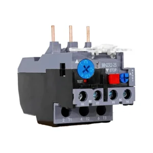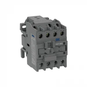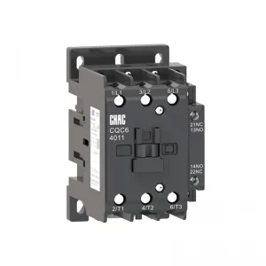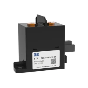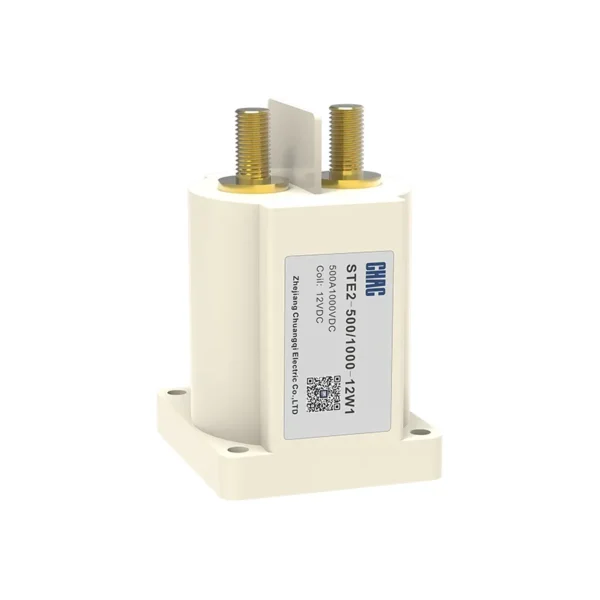
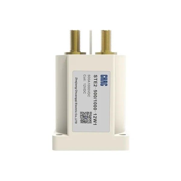
STE2 Series High-voltage DC contactor (Round Epoxy Sealing)
The STE2 Series High-voltage DC contactor (Round Epoxy Sealing) is a CHAC high-voltage DC contactor for controlled DC switching and isolation. The page keeps the model-specific technical table and original product images so buyers can verify voltage, current, configuration, mounting and applicable standards before ordering. Final suitability depends on the complete circuit, installation method and destination-market rules.
Product Overview
STE2 Series High-voltage DC contactor (Round Epoxy Sealing) is a high-voltage DC contactor intended for controlled DC switching and isolation. The current product record identifies it for battery, charging and high-voltage DC systems. Use the exact model variant and preserved technical source as the basis for procurement rather than assuming that every family member has the same rating.
Verified source summary: Type designation Product model Working voltage Working current Load polarity Coil polarity Auxiliary contact STE2-50 1500 50 Non-polarity Non-polarity / STE2-100 1500 100 Non-polarity Non-polarity / STE2-150 1500 150 Non-polarity Non-polarity / STE2-200 1500 200 Non-polarity Non-polarity 1NO STE2-250 1500 250 Non-polarity Non-polarity 1NO STE2-300 1500 300 Non-polarity Non-polarity 1NO STE2-400 1500 400 Non-polarity
Key Features
Typical Applications
Typical use can include battery, charging and high-voltage DC systems when the project confirms system voltage, current, fault or surge exposure, conductor and enclosure requirements, and the selected variant’s installation instructions. This page does not replace the project design or the authority having jurisdiction.
Applications and Selection Guide
Use the following decision points with the preserved model data. Product-family descriptions explain intent, but the exact technical table controls the ordered variant.
| Selection point | STE2 Series High-voltage DC contactor (Round Epoxy Sealing) | What the project must confirm |
|---|---|---|
| Application | High-Voltage DC Contactor projects | Confirm the actual system and environment |
| Selection basis | controlled DC switching and isolation | Use the exact model and technical table |
| Installation | Follow the model instructions | Check mounting, clearances and termination |
| Compliance | Use the listed standard where applicable | Verify edition, scope and destination rules |
| Adjacent product | Evaluate the related CHAC family where function differs | Do not substitute without engineering review |
Function
controlled DC switching and isolation
Match the protection or switching function to the system.
Configuration
Model-specific options
Confirm current, voltage, poles, terminals or accessories from the table.
Installation
Mechanical and electrical fit
Check enclosure, mounting, wiring space and maintenance access.
Project evidence
Documents and test records
Retain the approved drawing, technical sheet and commissioning record.
Ordering Guide
- State the exact model and variant.
- Provide the system voltage, current, frequency and load or protection function.
- Confirm mounting, terminals, accessories, enclosure and environmental conditions.
- Share quantity, destination market and required technical documents.
Installation and Coordination Checks
- Verify the model’s ratings and connection arrangement against the project drawings.
- Check conductor, busbar, enclosure, clearances and tightening requirements using the product documentation.
- Coordinate upstream and downstream protection or control devices where applicable.
- Use qualified personnel for installation, testing, isolation and maintenance.
Type designation
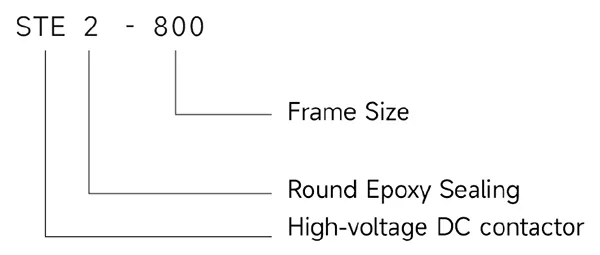
| Product model | Working voltage | Working current | Load polarity | Coil polarity | Auxiliary contact |
| STE2-50 | 1500 | 50 | Non-polarity | Non-polarity | / |
| STE2-100 | 1500 | 100 | Non-polarity | Non-polarity | / |
| STE2-150 | 1500 | 150 | Non-polarity | Non-polarity | / |
| STE2-200 | 1500 | 200 | Non-polarity | Non-polarity | 1NO |
| STE2-250 | 1500 | 250 | Non-polarity | Non-polarity | 1NO |
| STE2-300 | 1500 | 300 | Non-polarity | Non-polarity | 1NO |
| STE2-400 | 1500 | 400 | Non-polarity | Non-polarity | 1NO |
| STE2-500 | 1500 | 500 | Non-polarity | Non-polarity | 1NO |
| STE2-600 | 1500 | 600 | Non-polarity | Non-polarity | 1NO |
| STE2-800 | 1000 | 800 | Non-polarity | Non-polarity | 1NO |
Technical Specifications
| Product model | STE2-50 | STE2-100 | |
| Contact form | 1H | 1H | |
| Auxiliary contact | / | NO | |
| Contact polarity | Non-polarity | Non-polarity | |
| Contact resistance | ≤1mΩ(at 50A) | ≤1mΩ(at 100A) | |
| Operating voltage | ≤75%Un | ≤75%Un | |
| Maximum breaking current | 50A | 100A | |
| Electrical endurance | 12~1500V | 12~1500V | |
| Maximum breaking current | 500A(320V DC) | 1000A(320V DC) | |
| Electrical endurance | ≥1×10³ times(50A/750VDC) ≥400 times(20A/1000VDC) ≥150 times(10A/1500VDC) |
≥2×10³ times(100A/750VDC) ≥1×10³ times(100A/1000VDC) ≥600 times(15A/1500VDC) |
|
| Current carrying | 50A:Continuous for 100A:10min 200A:50s |
100A:Continuous for 150A:10min 300A:50s |
|
| Dielectric withstand voltage | Between open contacts | 3500VAC | 3500VAC |
| Between contact coils | 3500VAC | 3500VAC | |
| Mechanical Endurance | 2×10⁵ times | 2×10⁵ times | |
| Coil Voltage | 12V,24V | 12V,24V,48V | |
| Coil power consumption | 12V:5.5W 24V:6W | 12V:5.5W 24V:6.0W | |
| Load extraction method | Internal thread | Internal thread | |
| Coil lead out method | lead wire | lead wire | |
| Weight | About 115g | About 160g | |
| Vibrate | 80Hz~2000Hz 49m/s² | 80Hz~2000Hz 49m/s² | |
| Humidity | 5%~95%RH | 5%~95%RH | |
| Humidity range | -45℃~+85℃ | -45℃~+85℃ | |
| External dimensions (mm) | 51.6×35.6×43.2 | 53.8×35.6×58.5 | |
Note:
1.The above parameters are all initial values,measured at room temperature of 23℃.
2.Unless otherwise specified,the electrical durability tests are conducted on resistive loads with a on/off ratio of 0.6s:5s.
| Product model | STE2-150 | STE2-200 | STE2-250 | |
| Contact form | 1H | 1H | 1H | |
| Auxiliary contact | NO | NO | NO | |
| Contact polarity | Non-polarity | Non-polarity | Non-polarity | |
| Contact resistance | ≤1mΩ(at 150A) | ≤1mΩ(at 200A) | ≤1mΩ(at 250A) | |
| Operating voltage | ≤75%Un | ≤75%Un | ≤75%Un | |
| Maximum breaking current | 150A | 200A | 250A | |
| Electrical endurance | 12~1500V | 12~1500V | 12~1500V | |
| Maximum breaking current | 1000A(320VDC) | 2000A(320VDC) | 2000A(320VDC) | |
| Electrical endurance | ≥2×10³ times(100A/750VDC) ≥1×10³ times(150A/1000VDC) ≥600 times(30A/1500VDC) |
≥2×10³ times(200A/750VDC) ≥1×10³ times(200A/1000VDC) ≥1×10³ times(50A/1500VDC) |
≥2×10³ times(250A/750VDC) ≥1×10³ times(250A/1000VDC) ≥1×10³ times(50A/1500VDC) |
|
| Current carrying | 150A:Continuous for 180A:10min 300A:50s |
200A:Continuous for 300A:10min 400A:180s |
250A:Continuous for 300A:10min 400A:180s |
|
| Dielectric withstand voltage | Between open contacts | 3500VAC | 3500VAC | 3500VAC |
| Between contact coils | 3500VAC | 3500VAC | 3500VAC | |
| Mechanical Endurance | 2×10⁵ times | 2×10⁵ times | 2×10⁵ times | |
| Coil Voltage | 12V,24V,36V,48V | 12V,24V,36V,48V | 12V,24V,36V,48V | |
| Coil power consumption | 12V,24V,48V:5.76W 36V:2.5W | 6W | 6W | |
| Load extraction method | External thread | External thread | External thread | |
| Coil lead out method | lead wire | lead wire | lead wire | |
| Weight | About 430g | About 430g | About 430g | |
| Vibrate | 80Hz~2000Hz 49m/s² | 80Hz~2000Hz 49m/s² | 80Hz~2000Hz 49m/s² | |
| Humidity | 5%~95%RH | 5%~95%RH | 5%~95%RH | |
| Humidity range | -45℃~+85℃ | -45℃~+85℃ | -45℃~+85℃ | |
| External dimensions (mm) | 53.8×35.2×59.5 | 80.5×63.6×73.8 | 80.5×63.6×73.8 | |
Note:
1.The above parameters are all initial values,measured at room temperature of 23℃.
2.Unless otherwise specified,the electrical durability tests are conducted on resistive loads with a on/off ratio of 0.6s:5s.
| Product model | STE2-300 | STE2-400 | |
| Contact form | 1H | 1H | |
| Auxiliary contact | NO | NO | |
| Contact polarity | Non-polarity | Non-polarity | |
| Contact resistance | ≤1mΩ(at 300A) | ≤1mΩ(at 400A) | |
| Operating voltage | ≤75%Un | ≤75%Un | |
| Maximum breaking current | 300A | 400A | |
| Electrical endurance | 12~1500V | 12~1500V | |
| Maximum breaking current | 2000A(320V DC) | 2500A(320V DC) | |
| Electrical endurance | ≥2×10³ times(300A/750VDC) ≥1×10³ times(300A/1000VDC) ≥1×10³ times(80A/1500VDC) |
≥3×10³ times(400A/750VDC) ≥1×10³ times(400A/1000VDC) ≥1×10³ times(200A/1500VDC) |
|
| Current carrying | 300A:Continuous for 350A:10min 400A:180s |
400A:Continuous for 500A:10min 600A:180s |
|
| Dielectric withstand voltage | Between open contacts | 3500VAC | 3500VAC |
| Between contact coils | 3500VAC | 3500VAC | |
| Mechanical Endurance | 2×10⁵ times | 2×10⁵ times | |
| Coil Voltage | 12V,24V,36V,48V | 12V,24V,36V | |
| Coil power consumption | 6W | 3W | |
| Load extraction method | External thread | External thread | |
| Coil lead out method | lead wire | lead wire | |
| Weight | About 430g | About 990g | |
| Vibrate | 80Hz~2000Hz 49m/s² | 80Hz~2000Hz 49m/s² | |
| Humidity | 5%~95%RH | 5%~95%RH | |
| Humidity range | -45℃~+85℃ | -45℃~+85℃ | |
| External dimensions (mm) | 80.5×63.6×73.8 | 66.6×78.1×104.5 | |
Note:
1.The above parameters are all initial values,measured at room temperature of 23℃.
2.Unless otherwise specified,the electrical durability tests are conducted on resistive loads with a on/off ratio of 0.6s:5s.
| Product model | STE2-500 | STE2-600 | STE2-800 | |
| Contact form | 1H | 1H | 1H | |
| Auxiliary contact | NO | NO | NO | |
| Contact polarity | Non-polarity | Non-polarity | Non-polarity | |
| Contact resistance | ≤1mΩ(at 500A) | ≤1mΩ(at 600A) | ≤1mΩ(at 800A) | |
| Operating voltage | ≤75%Un | ≤75%Un | ≤75%Un | |
| Maximum breaking current | 500A | 600A | 800A | |
| Electrical endurance | 12~1500V | 12~1500V | 12~1500V | |
| Maximum breaking current | 2500A(320VDC) | 2500A(320V DC) | 2500A(320V DC) | |
| Electrical endurance | ≥2×10³ times(500A/750VDC) ≥1×10³ times(500A/1000VDC) ≥1×10³ times(250A/1500VDC) |
≥2×10³ times(600A/750VDC) ≥1×10³ times(600A/1000VDC) ≥1×10³ times(300A/1500VDC) |
≥600 times(800A/750VDC) ≥1×10³ times(450A/1000VDC) ≥200 times(350A/1500VDC) |
|
| Current carrying | 500A:Continuous for 550A:10min 600A:180s |
600A:Continuous for 650A:10min 700A:180s |
800A:Continuous for 900A:10min 1000A:120s |
|
| Dielectric withstand voltage | Between open contacts | 3500VAC | 3500VAC | 3500VAC |
| Between contact coils | 3500VAC | 3500VAC | 3500VAC | |
| Mechanical Endurance | 2×10⁵ times | 2×10⁵ times | 2×10⁵ times | |
| Coil Voltage | 12V,24V,36V | 12V,24V,36V | 12V,24V,36V | |
| Coil power consumption | 3W | 3W | 3W | |
| Load extraction method | External thread | External thread | External thread | |
| Coil lead out method | lead wire | lead wire | lead wire | |
| Weight | About 990g | About 990g | About 990g | |
| Vibrate | 80Hz~2000Hz 49m/s² | 80Hz~2000Hz 49m/s² | 80Hz~2000Hz 49m/s² | |
| Humidity | 5%~95%RH | 5%~95%RH | 5%~95%RH | |
| Humidity range | -45℃~+85℃ | -45℃~+85℃ | -45℃~+85℃ | |
| External dimensions (mm) | 66.6×78.1×104.5 | 66.6×78.1×104.5 | 66.6×78.1×104.5 | |
Note:
1.The above parameters are all initial values,measured at room temperature of 23℃.
2.Unless otherwise specified,the electrical durability tests are conducted on resistive loads with a on/off ratio of 0.6s:5s.
Why Choose CHAC
With 30+ years of manufacturing experience, 1100+ employees, 100M+ poles
annual capacity and 90% automated production, CHAC provides stable production capacity and strict
quality control for global OEM/ODM customers. Our in-house manufacturing system supports long-term
cooperation for electrical brands, importers and distributors.

30+
YEARS EXPERIENCE
Specialized in low-voltage electrical manufacturing

1100+
EMPLOYEES
Professional team ensures stable quality and delivery

100M+
POLES ANNUAL CAPACITY
Large-scale production capacity to meet global demand

90%
AUTOMATED PRODUCTION
Advanced automation for high efficiency and consistency
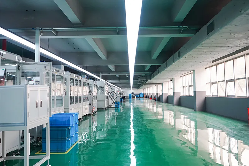
Automated Assembly Line

Testing Laboratory
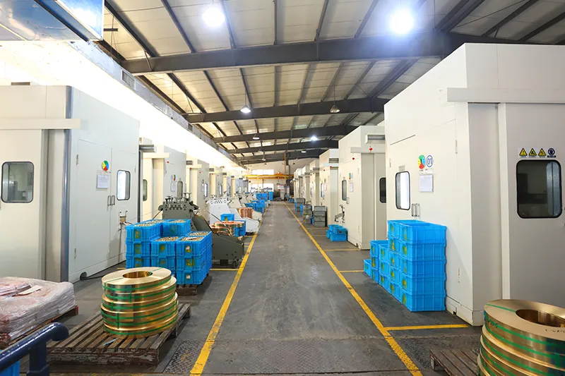
Injection & Stamping
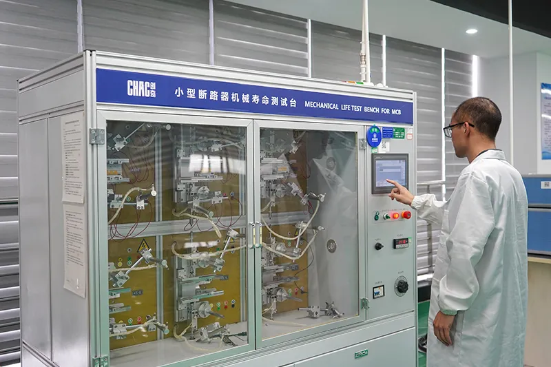
Quality Inspection



Strict quality control system ensures every product meets global standards.
What Can We Customize?
CHAC supports customization of coil voltage, auxiliary contact configuration,
electrical parameters, product branding,packaging design and engineering development according to customers’ equipment and market requirements.

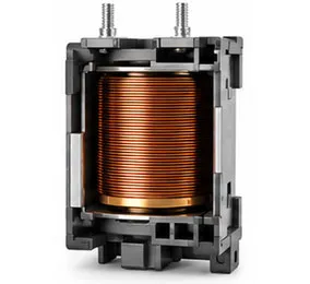
Coil Voltage
AC and DC coil voltage options tailored to application requirements.

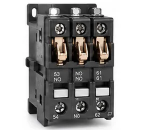
Auxiliary Contacts
Flexible auxiliary contact combinations for different control functions.

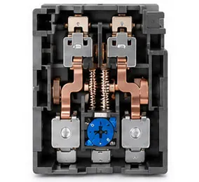
Electrical Parameters
Current ratings, protection ranges and functional parameters can be customized.

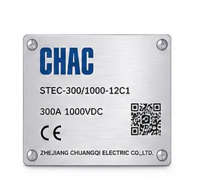
Product Branding
Private label logos, nameplates and product identification support.

Packaging Design
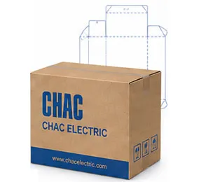
Custom cartons, labels, manuals and packaging solutions.

Engineering Development
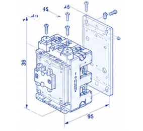
Support from drawing optimization to product development and application matching.
Download
STE Series High Voltage DC Contactor
Complete product overview for low-voltage electrical components and product selection reference.
Need Technical Documents?
Contact us for datasheets, certificates, drawings, selection guidance or OEM/ODM project support.
STE2 Product FAQ
What is the STE2 used for?
It is a high-voltage DC switching device for the system and variant shown in the technical table. Confirm the working voltage, current, polarity and load category.
Why does DC contactor polarity matter?
Some variants specify load or coil polarity because DC arc management and magnetic blowout depend on the internal design. Follow the marked polarity.
How do I select the voltage and current?
Use the actual steady, inrush and breaking current, system voltage, duty cycle and fault-clearing strategy. The family range is not a blanket rating for every variant.
What does ceramic or epoxy sealing change?
The sealing construction is part of the product design and environmental suitability. Compare the exact datasheet for temperature, insulation and endurance.
Can it switch a battery or charger circuit?
It may be suitable when the variant's DC voltage, current, breaking duty and insulation data match the application. Confirm the complete design.
What should be tested before energizing?
Check coil operation, contact resistance, insulation, polarity, pre-charge or discharge sequence and the emergency isolation procedure.
Confirm the Right STE2 Configuration
Send the exact model, operating conditions, quantity, destination market and required documents. CHAC will review the request against the published product data.