Considérons ce problème de mise en service hypothétique : un ingénieur d’atelier à Dubaï ferme un armoire de distribution nouvellement câblée, et un circuit qui fonctionnait lors d’une vérification à portes ouvertes se met à disjoncter plus tard au cours du même poste. Le remplacement du disjoncteur par un appareil de même calibre ne permet pas d’expliquer la différence constatée. La question pertinente est de savoir ce qui a changé dans son environnement : la température de l’enveloppe, les charges voisines, l’état des câbles ou le raccordement lui-même. Une salle climatisée et un compartiment de disjoncteur chaud ne constituent pas le même environnement de fonctionnement.
Résumé : Le déclassement d’un disjoncteur consiste à utiliser le courant admissible du fabricant en fonction des conditions réelles d’installation. Le tableau de déclenchement publié pour le PXB6-63 utilise une température de référence de 30°C. Cette référence n’est ni une température ambiante maximale universelle ni un facteur de correction. Obtenez les données de température exactes relatives au calibre, évaluez l’enveloppe chargée et revérifiez la protection des câbles avant d’augmenter la taille du disjoncteur.
À quelle température devez-vous appliquer le dératement du disjoncteur ?
Le pertinent Classification thermique du disjoncteur Il doit être lu en tenant compte des conditions de référence indiquées. Un thermomètre mural mesure la température ambiante d’une pièce. Il ne permet pas de déterminer la température de l’air entourant un équipement à l’intérieur d’un armoire chargée, notamment à proximité d’une autre source de chaleur. De même, une image thermique d’une borne électrique renseigne sur une température de surface, qui ne peut pas être directement reportée dans un tableau de correction de la température ambiante.
Les caractéristiques de déclenchement publiées par PXB6-63 identifient 30°C comme la température de calibrage de référence. Le tableau distingue également une condition de démarrage à froid d’un essai effectué après une phase de charge précédente. Ces détails sont importants lors de l’interprétation du fonctionnement. Un multiple de courant et une limite de temps font partie d’une séquence d’essai spécifiée, plutôt que de décrire chaque condition de terrain.
Enregistrez l’emplacement où la température est mesurée, les circuits alimentés, l’état de la porte (ouverte ou fermée) ainsi que l’état normal de fonctionnement des ventilateurs et des filtres. Suivez les instructions du fabricant pour déterminer la méthode et le point de mesure appropriés. Le personnel qualifié doit planifier toute mesure effectuée à proximité d’équipements électriques ; ouvrir un coffret sous tension afin d’obtenir une valeur de mesure aisée ne constitue pas une méthode de mise en service.
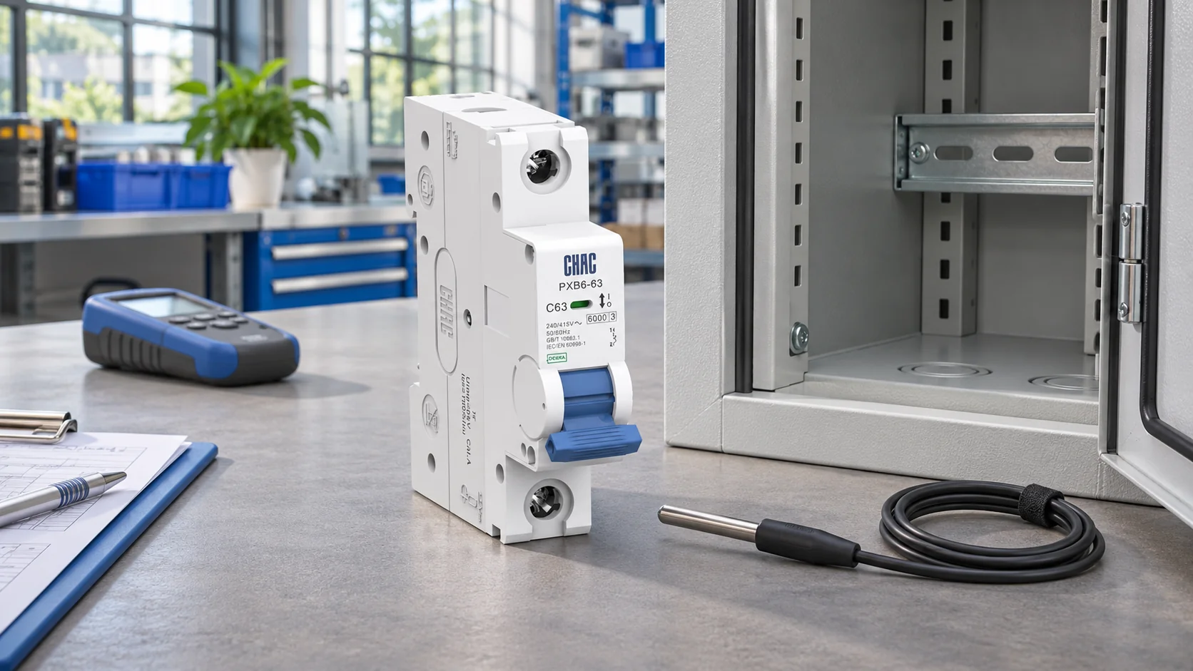
Vérifiez la dératisation du disjoncteur en tenant compte des limites de courant des câbles et des assemblages.
Réduction de la température addresses one influence on usable current. Conductor grouping, cable installation method, terminal suitability and the assembly’s temperature-rise performance introduce other limits. A correction intended for a cable cannot be applied to an MCB, and an MCB correction cannot establish the capacity of the complete panel.
IEC 61439-1:2020 expressly addresses assemblies and introduces group rated current in connection with temperature-rise verification. Its scope explains why checking one component does not settle the assembly question. Apply the relevant assembly part together with the general rules; the appropriate verification depends on the design and intended use.
| Question | Ce qu'il décrit | Des preuves nécessaires |
|---|---|---|
| What is the breaker rated current? | The selected device rating under its declared conditions | Exact model, poles, curve and rating |
| What current is permitted at this temperature? | The manufacturer’s temperature correction | Applicable table and its reference conditions |
| What can the cable carry? | Conductor capacity in its installation | Cable calculation including applicable corrections |
| What can the loaded assembly carry? | The enclosure and circuit arrangement together | Applicable assembly verification and loading assumptions |
Where a manufacturer explicitly defines a multiplicative factor, the arithmetic may be straightforward. For illustration only, a hypothetical factor of 0.90 applied to 32 A gives 28.8 A. This is not PXB6 correction data, a recommended load or evidence that several correction factors may be multiplied together. The manufacturer’s method determines whether and how those factors can be combined.
Investigate panel heating before increasing the breaker rating
Increasing a breaker from 32 A to 40 A changes the protection decision. It may leave the existing conductor insufficiently protected, even if it stops an inconvenient trip. Changing from curve B to C or D also changes the magnetic trip characteristic; it does not provide a general solution to heat-related overload behaviour. The B, C and D curve guide explains that separate selection issue.
Review the measured load profile and investigate abnormal heating or connection defects before treating every trip as a derating problem. A poorly made termination requires correction under the manufacturer’s installation instructions. More ventilation cannot make an unsuitable termination acceptable. Equally, a larger enclosure or revised spacing needs to be evaluated as an assembly change, including any effect on ingress protection and maintenance.
| État observé | Useful review | Avoid assuming |
|---|---|---|
| Operation changes after other circuits are loaded | Actual simultaneous loading and local thermal conditions | Every circuit can carry its headline current simultaneously |
| One termination is abnormally hot | Conductor, terminal condition and approved connection procedure | A general derating factor repairs a connection fault |
| Behaviour changes with the cabinet door open | Normal closed-door service conditions | An open-door trial validates the finished panel |
| A higher-current replacement is proposed | Cable protection, fault duty and assembly verification | A larger rating is an equivalent replacement |
The purchasing cost includes engineering time as well as hardware. A low-cost replacement followed by another site visit can cost more than resolving the enclosure design before manufacture. Compare corrective options by their effect on protection, assembly requirements, downtime and future servicing; do not select the cheapest component change in isolation.
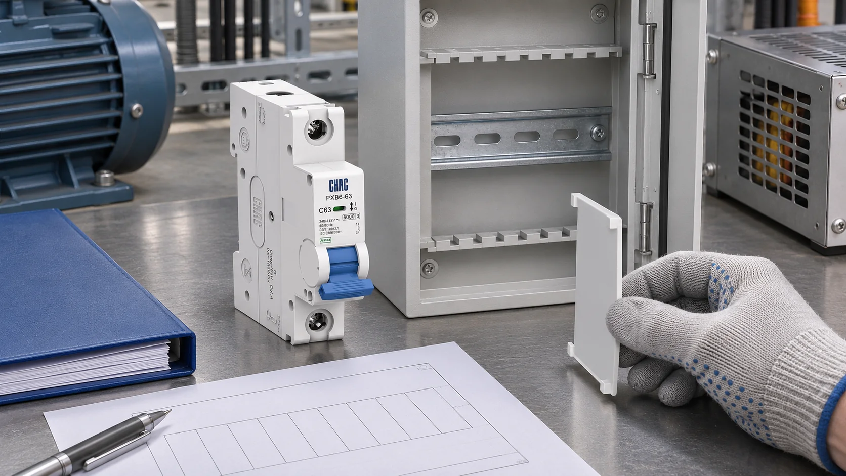
How to request temperature correction data for your PXB6 configuration
CHAC PXB6-63 product information lists current options from 6 A to 63 A, pole options from 1P to 4P, and B, C and D curves. Those choices identify different order configurations. The public 30°C tripping reference does not supply a complete current-versus-temperature table for every configuration.
Send the exact PXB6 designation, intended load, pole arrangement, local ambient-temperature estimate, enclosure arrangement and simultaneous-loading assumptions when requesting the applicable correction data. Ask whether the supplied method accounts for adjacent devices and whether additional assembly checks remain necessary. Keep the response and revision with the panel design.
IEC TR 61439-0:2022 provides guidance for specifying assembly functions and characteristics, including current-rating considerations. Use that specification discussion to agree the intended loading and service conditions with the assembly manufacturer. It is a technical report, not a product certificate or a source of a universal PXB6 correction factor.
IEC 60898-1 is the product-standard reference on the published PXB6 page. IEC 61439 addresses the assembly, while the applicable installation rules govern circuit and conductor protection. These are different scopes. A catalogue standard reference does not establish conformity of a modified panel or prove that an order carries every possible approval.
Common questions about PXB6 derating in hot panels
What does circuit breaker derating mean in a hot electrical panel?
It means limiting usable current according to the manufacturer’s data for the actual thermal conditions. It does not change the number printed on the breaker or automatically change its trip setting. The permitted circuit load must also satisfy conductor and assembly requirements.
Which ambient temperature should be used when reading a breaker’s derating table?
Use the ambient temperature and measurement conditions defined by that manufacturer’s table, normally relating to the environment around the device. Do not substitute room temperature or a measured terminal surface temperature without checking the instructions. Record the enclosure’s representative loaded condition.
How do adjacent devices and enclosure ventilation affect usable breaker current?
They can change the local thermal environment and the assembly’s temperature rise. The size of the effect depends on the actual arrangement, loading and approved correction method. Do not borrow a grouping factor from another product family.
Is temperature derating the same as changing the trip setting?
No. Derating concerns permitted use under particular conditions, while a trip setting determines a protection threshold where adjustment is available. A fixed-rating MCB does not acquire an adjustable overload setting because a correction table is used.
Where can I obtain the temperature correction data for the exact PXB6 rating?
Request it from CHAC with the complete model, current, curve, poles and panel conditions. Ask for the applicable document revision and any limits on using it. The published reference-temperature tripping table alone is insufficient to calculate every high-temperature operating case.
Can one temperature derating factor be applied to every MCB model?
No. Different products can have different reference conditions and thermal behaviour. Apply a factor only to the models and arrangements covered by its source, including any stated restrictions.
What assembly conditions should be checked before increasing a breaker rating?
Check the design load, cable capacity, terminations, simultaneous loading, enclosure ventilation, fault duty and coordination. Review the applicable assembly verification and local installation requirements. Resolve the cause of the original trip before approving a larger protective device.
Références
- IEC 61439-1:2020: assembly service conditions and verification, including group rated current.
- IEC 60947-2:2024: circuit-breaker scope for instructed or skilled users; a separate product-standard context.
- IEC TR 61439-0:2022: guidance for specifying assemblies.
The published PXB6-63 technical data linked above supplies the model range and the 30°C test reference. No PXB6-specific high-temperature correction factor is asserted in this article.
Specify the load and the conditions around the device together. For a PXB6 review, send CHAC your configuration and panel conditions so the appropriate technical information can be confirmed before ordering.