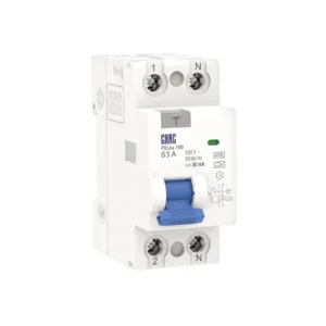
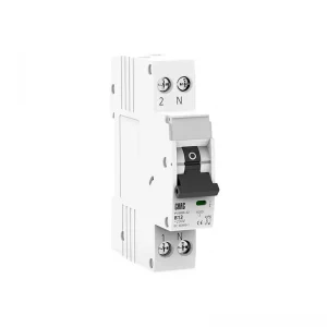
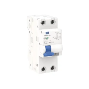
CQB7R-125 Series Prepaid Energy Meter External Circuit Breaker
The CQB7R-125 is specified for overload and short-circuit protection with prepaid-meter control functions. Select it using the published voltage, current, pole and protection data, then confirm conductor coordination, fault conditions, enclosure requirements and local installation rules.
Product Overview
CQB7R-125 is a prepaid meter circuit breaker for 30/400V AC by pole arrangement applications. It is intended for prepaid-meter panels where the utility or project control scheme supports the function; this describes an evaluation context, not a universal approval. Confirm the complete circuit design before specifying the product.
overload and short-circuit protection with prepaid-meter control functions is distinct from adjacent protection functions. Do not infer AC/DC suitability, residual-current protection, automatic control or isolation performance from the product family name alone.
Key Features
Typical Applications
prepaid-meter panels where the utility or project control scheme supports the function. Verify system voltage, expected fault current or leakage, wiring arrangement, environment, coordination and applicable rules for the ordered configuration.
Applications and Selection Guide
Use the verified CQB7R-125 records below to create a shortlist. Product labels do not replace the project calculation, coordination review or exact installation instructions.
| Selection point | CQB7R-125 reference | What the project must confirm |
|---|---|---|
| Rated current | Use the exact model table | Design current, conductor capacity, ambient and grouping |
| Voltage and frequency | 30/400V AC by pole arrangement | Supply system and equipment rating |
| Poles | 2P / 4P | Conductors to be switched, protected or isolated |
| Protection / control | overload and short-circuit protection with prepaid-meter control functions | Required function and adjacent-device coordination |
| Fault / residual data | B/C/D curves and automatic trip/close timing from the technical table | Prospective short-circuit or leakage conditions |
Local Protection and Smart Control
Remote monitoring or automatic control does not replace local protection, isolation and commissioning procedures. Verify network, control and fallback behaviour.
Control Architecture
Request Technical Support →
Model-Specific Ratings
Use the exact technical table for rated voltage, current, poles, terminals, life and environmental limits.
Verified Data
View Technical Support →
Installation and Coordination
Check the complete circuit, conductor sizing, fault or leakage conditions, enclosure and local rules before energising.
Engineering Check
Discuss a Configuration →
Ordering Information
State model, rating, poles, system, quantity, destination market and document requirements so the configuration can be reviewed.
Project Inputs
Send Project Details →
Ordering Guide
- State the exact model: CQB7R-125.
- Provide rated current and voltage from the published technical table.
- Confirm poles and the required protection, isolation or control function.
- Provide application, expected fault/leakage conditions, destination market and quantity.
- List accessory, terminal, documentation and approved marking or packaging requirements.
Installation and Coordination Checks
- Use the exact model drawing and instructions; do not infer wiring or accessory compatibility from another product.
- Verify conductor size, terminal torque, enclosure conditions, temperature, grouping and clearances.
- Coordinate upstream and downstream devices and confirm the required fault, leakage or voltage response.
- Installation, testing and maintenance must be completed by qualified personnel under applicable rules.
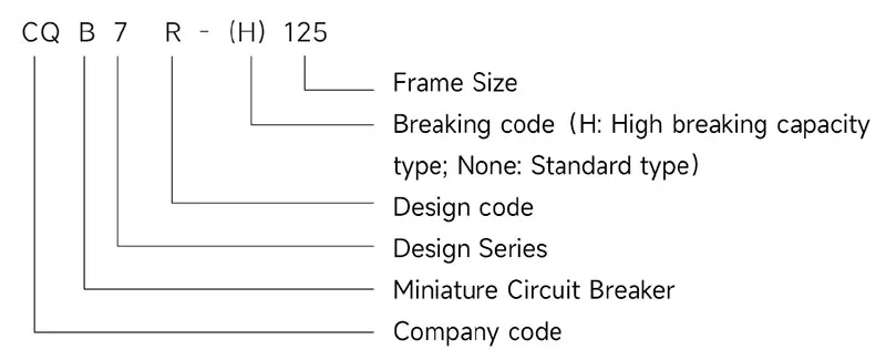
Type designation
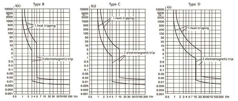
Tripping curves
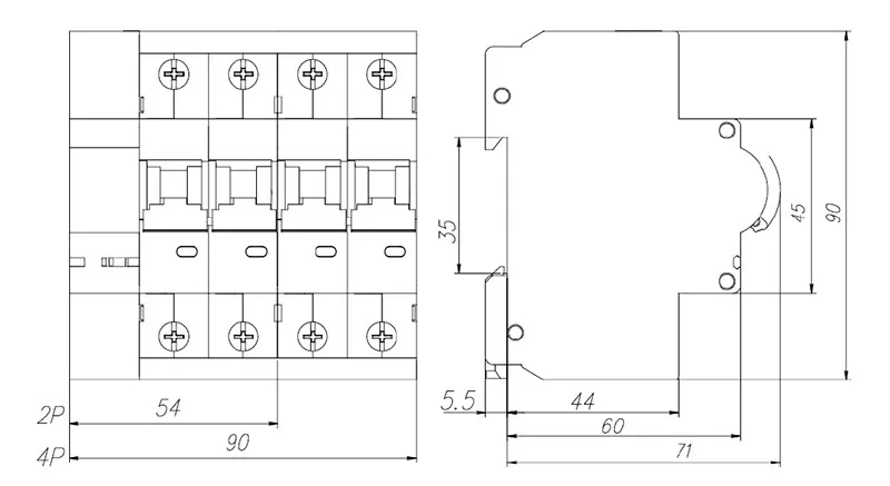
Dimensions(mm)
Technical Specifications
| Parameter | |
| Rated voltage (V) | 30V~(2P), 400V~(4P) |
| Rated current (A) | 40,50,63,80,100,125 |
| Rated impulse withstand voltage Uimp(V) | 6000V |
| Rated frequency | 50Hz/60Hz |
| Polar number | 2P,4P |
| Rated short-circuit capacity lcn(A) | 6kA, 10kA(high breaking score) |
| Operating short-circuit capacity Ics(A) | 6kA,7.5kA (high break type) |
| Mechanical and electrical life (times) | Mechanical life ≥ 10,000, electrical life ≥ 6,000 |
| Instantaneous tripping type | B,C,D |
| Tightening torque (N.m) | 3.5 |
| Automatic closing time (tc) | t ≤ 3s |
| Automatic opening time (td) | t ≤ 2s |
| Pollution level | Level 2 |
| Protection grade | IP20 |
| Installation category | Ⅲ |
| Meet the standards | IEC60898-1, GB10963-1 |
| Certification | CCC |
Tripping characteristics (Reference temperature 30℃)
| Item | Tripping Curve | Test current In(A) | Initial Status | Time limit for tripping or non-tripping | Expected result | Remarks |
| a | B, C, D | 1.13In | Cold | t ≤ 1h | Non-tripping | Current smoothly rises to specified value within 5s |
| b | B, C, D | 1.45In | Following item a test | t < 1h | Tripping | |
| c | B, C, D | 2.55In | Cold | 1s < t < 60s (In ≤ 32A) 1s < t < 120s (In > 32A) |
Tripping | |
| d | B | 3In | Cold | t ≤ 0.1s | Non-tripping | Switch on the power supply by closing the auxiliary switch |
| C | 5In | |||||
| D | 10In | |||||
| e | B | 5In | Cold | t < 0.1s | Tripping | Switch on the power supply by closing the auxiliary switch |
| C | 10In | |||||
| D | 20In |
Note: The term “cold” means that the test is carried out at a refererce calibration temperature without load before the test
Conductor requirements and cross section
| Copper cross-section(mm2) | Rated current In(A) |
| 10 | 32<In≤50 |
| 16 | 50<In≤63 |
| 25 | 63<In≤80 |
| 35 | 80<In≤100 |
| 50 | 100<In≤125 |
Why Choose CHAC
With 30+ years of manufacturing experience, 1100+ employees, 100M+ poles
annual capacity and 90% automated production, CHAC provides stable production capacity and strict
quality control for global OEM/ODM customers. Our in-house manufacturing system supports long-term
cooperation for electrical brands, importers and distributors.

30+
YEARS EXPERIENCE
Specialized in low-voltage electrical manufacturing

1100+
EMPLOYEES
Professional team ensures stable quality and delivery

100M+
POLES ANNUAL CAPACITY
Large-scale production capacity to meet global demand

90%
AUTOMATED PRODUCTION
Advanced automation for high efficiency and consistency
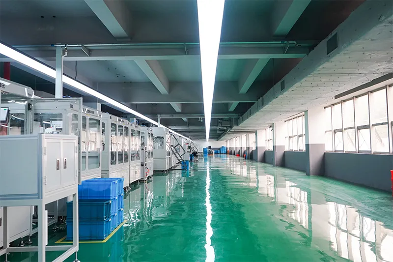
Automated Assembly Line

Testing Laboratory
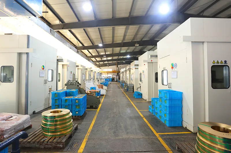
Injection & Stamping
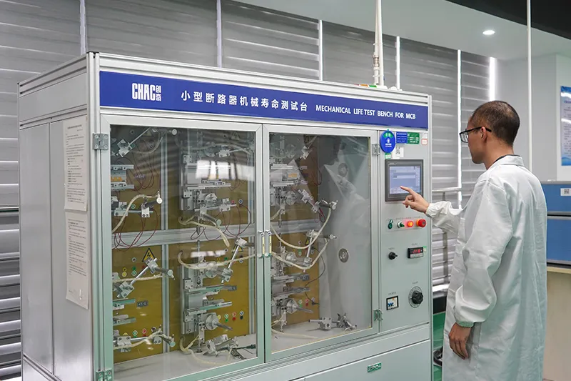
Quality Inspection



Strict quality control system ensures every product meets global standards.
What Can We Customize?
For CQB7R-125 projects, CHAC can review private-label marking, packaging, approved appearance options and the published electrical configurations. Requests outside the published range require engineering evaluation, testing and feasibility review.

Logo & Branding
Custom logo printing, laser marking and nameplate solutions.


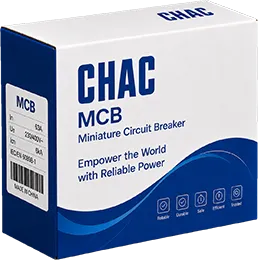
Packaging
Customization
Customized color boxes, cartons, labels and manuals.

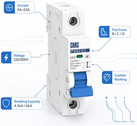
Electrical
Customization
Current, voltage, breaking capacity, trip curve and other
special functions.

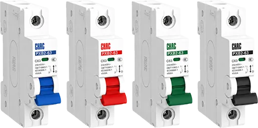
Product
Appearance
Housing color, handle color and appearance customization.

Certification
Support
Products comply with international standards and market
requirements.


Engineering
Development
Drawing evaluation, prototype testing and mass production.

Download
PXB9 Series Miniature Circuit Breaker
Complete product overview for low-voltage electrical components and product selection reference.
Need Technical Documents?
Contact us for datasheets, certificates, drawings, selection guidance or OEM/ODM project support.
CQB7R-125 Product FAQ
What is the CQB7R-125 used for?
The CQB7R-125 is specified for overload and short-circuit protection with prepaid-meter control functions in 30/400V AC by pole arrangement applications, within the ratings and configurations listed in its technical table. Final suitability depends on the complete circuit design.
How does the CQB7R-125 support prepaid-meter control?
The page lists external prepaid-meter use with automatic tripping and closing. Confirm the meter interface, control sequence, timing and utility or project requirements before installation.
How do I choose the CQB7R-125 rating and poles?
Start with the design current and system arrangement, then choose only a published option. The page lists pole options as 2P / 4P; confirm neutral, polarity, conductors and isolation requirements.
What safety limitation applies to the CQB7R-125?
Do not treat the CQB7R-125 as a universal substitute for another device. Confirm B/C/D curves and automatic trip/close timing from the technical table, the system voltage, fault or leakage conditions and any separate upstream protection before selection.
Can the CQB7R-125 be used in another circuit type?
Only when the exact ordered configuration is rated for that circuit. AC and DC duties, residual-current devices, isolators, smart controls and voltage protectors are not interchangeable by appearance or current rating.
How should the CQB7R-125 be installed and tested?
Use the exact product drawing, terminal identification and instructions. A qualified person should verify isolation, conductors, torque, settings, coordination and functional tests before energising the circuit.
Confirm the Right CQB7R-125 Configuration
Send the model, rating, poles, system voltage, application, quantity and document requirements. CHAC will review the request against the published data.