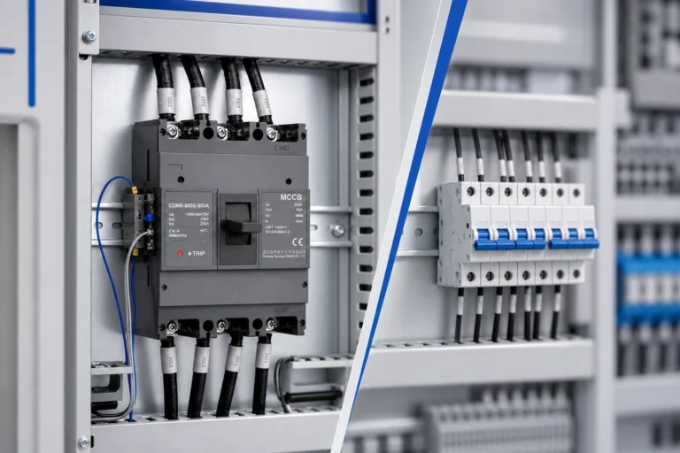
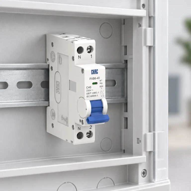
A two-pole or four-pole RCCB starts with the conductors and supply arrangement shown on the approved panel drawing. The selected model, voltage, residual-current fields, and project documents then determine whether the proposed option belongs in the final panel review.
Contents
Part 1. Begin with the supply arrangement on the drawing
Two-pole versus four-pole RCCB review begins before a product is selected. Read the supply arrangement, the conductors brought through the protective device, and the circuit boundary on the panel drawing. Those inputs establish which pole arrangement can be evaluated further.
Panel space may affect layout, but it is not the primary selector. The circuit sketch, neutral treatment, and selected-device documentation give the procurement team a defensible basis for comparing proposed options.
Part 2. What the pole count does and does not decide
Pole count describes the device arrangement being considered; it does not by itself prove suitability for a distribution panel. A selected model must be matched to the supply arrangement, voltage, conductor path, residual-current characteristics, and project requirements.
Manufacturer documentation and the IEC standards system help frame the document review. They do not replace the approved panel design or authorize an installation without the selected-model evidence.
Important: Do not select a 2P or 4P RCCB by matching the enclosure width or a product photo. Confirm the supply arrangement and conductors in the drawing, then verify the selected-model documentation. (IEC residual-current-device document catalog — selected-device record context)
Part 3. Compare 2P and 4P review inputs side by side
The comparison is useful when it forces the same questions for each option. It should not be read as a universal wiring diagram or as a rule that one pole arrangement fits every panel.
| Review input | 2P option review | 4P option review |
|---|---|---|
| Supply arrangement | Identify the supplied conductors on the drawing | Identify the supplied conductors on the drawing |
| Neutral path | Show how neutral is represented in the circuit record | Show how neutral is represented in the circuit record |
| Voltage | Match the stated circuit voltage to selected-model data | Match the stated circuit voltage to selected-model data |
| Residual-current fields | Request type and sensitivity for the project | Request type and sensitivity for the project |
| Product documents | Confirm poles, terminals, limits, and instructions | Confirm poles, terminals, limits, and instructions |
Document both the supply arrangement and the selected model in the same review record. This avoids changing the pole count on a bill of materials without revisiting the conductors and technical evidence that led to it.
Part 4. Keep neutral, voltage, and residual-current fields together
Neutral treatment should be visible in the drawing discussion, not added after an option has been priced. Pair it with the stated circuit voltage, residual-current type, residual-current sensitivity, and rated-current requirement. The resulting evidence set makes questions for the supplier specific.
| Evidence to provide | Why the supplier needs it | Result to compare |
|---|---|---|
| Panel circuit sketch and revision | Identifies supply and conductor scope | Proposed pole arrangement tied to the drawing |
| Neutral treatment | Prevents an incomplete conductor-path assumption | Selected-model terminal and pole information |
| Circuit voltage and current requirement | Defines the electrical review | Published selected-model fields |
| Residual-current type and sensitivity request | States the protection characteristic to be reviewed | Product documentation matching the request |
| Enclosure and installation context | Identifies conditions requiring confirmation | Stated installation information and limits |
For sensitivity-specific context, read the related 30mA versus 10mA RCCB selection guide. The choice between RCCB and RCBO remains a separate functional decision covered in the RCBO versus RCCB selection boundary article.
Part 5. Turn the panel evidence into a clear supplier request
Request a response that identifies the proposed model and the documents used to compare it. A clean request reduces the temptation to select an RCCB from a photo, a pole-count label, or an incomplete BOM line.
Ask the supplier to review the current drawing revision, supply arrangement, neutral treatment, required voltage and current fields, residual-current type and sensitivity, enclosure context, and any requested documentation. The RCCB category provides the upward product-family context, while the terminal electrical appliances range provides broader component navigation.
Part 6. Use the CHAC RCCB route for selected-model review
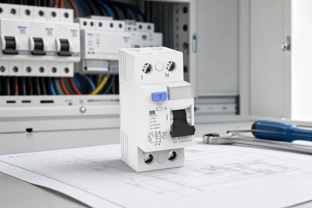
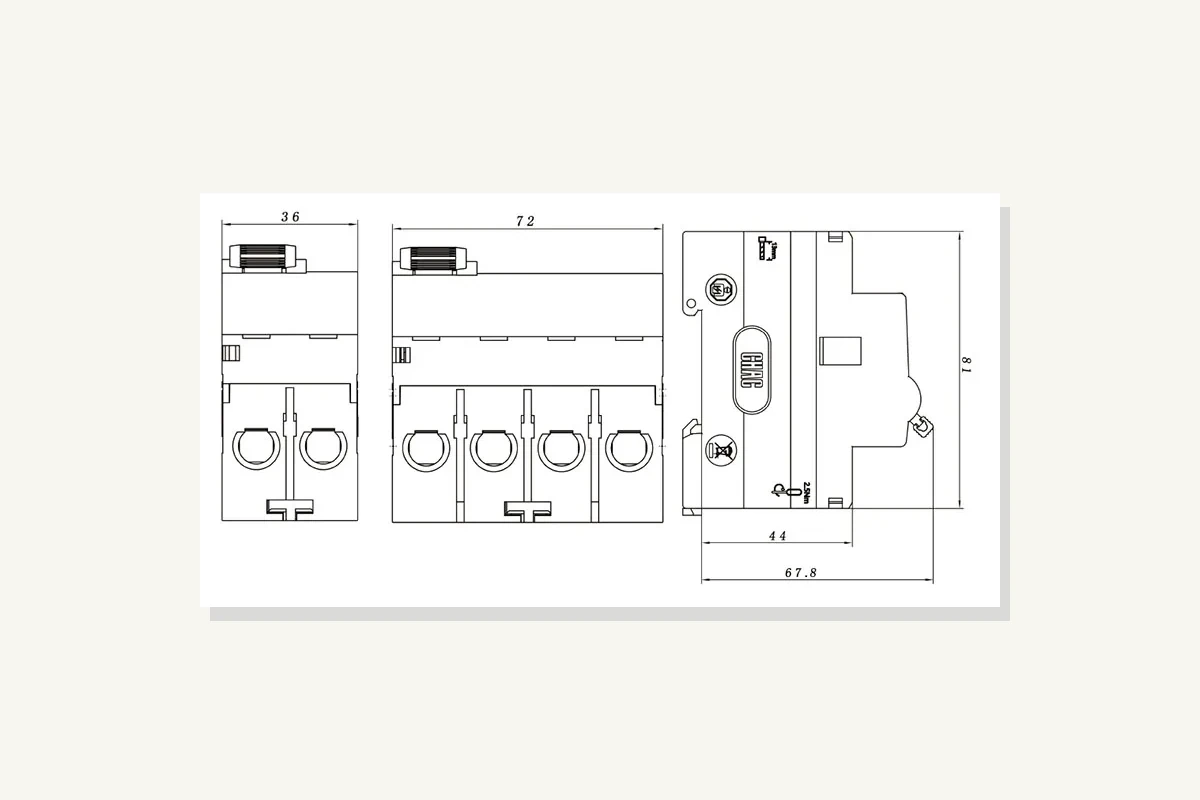
The PXL6a-100 RCCB product route publicly lists 2P and 4P options, 230/400V AC, residual-current fields, and IEC 61008-1. Use those published fields to begin a selected-model review after the panel evidence is complete, not as a shortcut to approve a panel.
Product recommendation
PXL9-63 Series Electromagnetic Leakage Circuit Breaker RCBO | CHAC Electric

Use this RCCB product route when the RFQ has already established the supply arrangement and required evidence. Do not replace it with an RCBO or an image-only match: the protection-function boundary, pole arrangement, voltage, residual-current data, and project fit still need their own confirmation. OEM or documentation requirements can be raised through the terminal-electrical customization page.
Part 7. Keep this comparison inside its fit boundary
This article supports an early distribution-panel review and a better supplier conversation. It is not live-work guidance, a local installation interpretation, a protection-coordination study, or a reason to substitute an RCCB for an RCBO.
Fit Boundary: retain final selection with the approved panel drawing, selected-model documents, applicable project requirements, and qualified engineering review. Send the circuit sketch and required evidence to CHAC Electric when requesting a documented product route.
FAQs
What is the difference between a 2P and 4P RCCB?
They are different pole arrangements that must be reviewed against the supply arrangement and conductors in the panel drawing. The selected model and project documents determine the final fit.
Can a 2P RCCB be used on a three-phase panel?
Do not infer that from a pole-count label. Review the supply arrangement and circuit boundary shown on the approved design, then confirm the selected-device documentation.
Does a 4P RCCB always include a neutral pole?
Check the selected model and the panel drawing. Neutral treatment must be documented with the product route rather than assumed from a general description.
Which conductors must pass through an RCCB?
The approved circuit design establishes the conductor path. Show that path and the neutral treatment in the supplier review instead of relying on a generic diagram.
What voltage and residual-current data should a buyer send?
Send the stated circuit voltage, current requirement, requested residual-current type and sensitivity, plus the current panel drawing revision and installation context.
Is an RCBO interchangeable with an RCCB?
No automatic interchange should be assumed. Their protection-function boundary requires a separate review alongside the project requirements and selected-model documents.