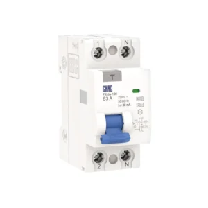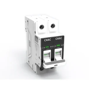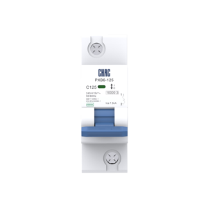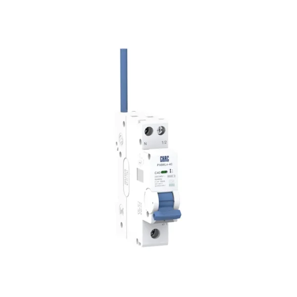
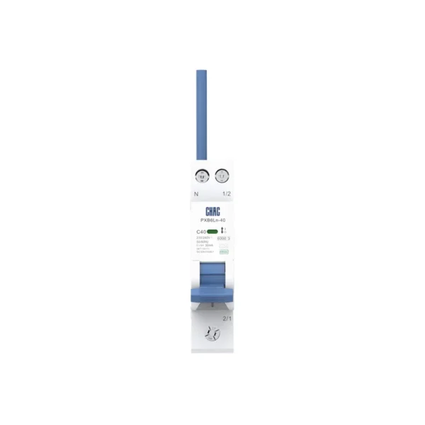
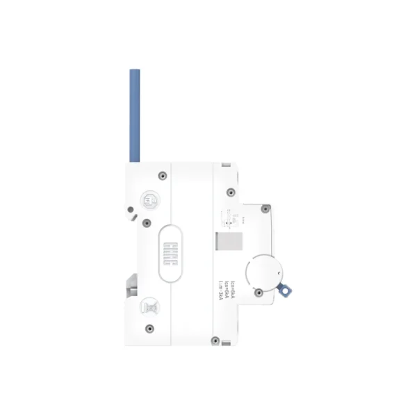
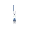
PXB6Ln-40 Electronic Residual Current Operated Circuit-Breaker with Overcurrent Protection
Product Features
■ Enhanced Safety Design: Compact enclosure with a 1P+N configuration and simultaneous disconnection for improved maintenance safety.
■ Dual Electrical Protection: Integrated overload and short-circuit protection provides reliable basic protection for distribution circuits.
■ Safe Isolation: Reliable electrical isolation with a clearly indicated open position ensures complete circuit isolation for safe maintenance.
■ Wide Application Range: Suitable for circuit protection in industrial, commercial, high-rise residential, and household electrical systems.
Ordering Specification
Please specify the following when ordering:
1.Product Model: PXB6Ln-40
2.Number of Poles: 1P+N,
3.Rated Current & Tripping Curve: e.g., C/25A
- Tripping Curve (Type): B, C
- Rated Current (In): 6A, 10A, 16A, 20A, 25A, 32A,40A
4.Residual Current Operation:
- Residual Current Type: AC, A
- Rated Residual Operating Current (IΔn): 10mA, 30mA,100mA,
Quantity: e.g., 100 pcs
5.Ordering Example:
PXB6Ln-40 1P+N C/25A 30mA AC 100 pcs
Technical Specifications
| Parameter | |
| Rated Voltage | 230/240V |
| Rated Insulation Voltage(Ui) | 400V |
| Rated Impulse Withstand Voltage (Uimp) | 4000V |
| Rated Current (In) | 6、10、16、20、25、32、40 |
| Rated Residual Operating Current(IΔn) | 10、30、100mA |
| Residual Current Trip Type | AC type、A type |
| Rated Frequency | 50/60Hz |
| Number of Poles | 1P+N |
| Rated Short-Circuit Breaking Capacity (Icn = Ics) | 6000A |
| Mechanical Endurance | ≥10000 |
| Electrical Endurance | ≥4000 |
| Instantaneous Tripping Type | B、C |
| Grid Spacing | 50mm |
| Degree of Protection | IP 20 |
| Standards Compliance | IEC61009-1, GB/T 16917.1 |
| Certification | CE CB CCC |DEKRA Certified |
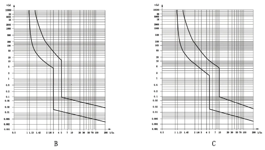
Tripping Characteristics (Reference Temperature: 30℃)
| Item | Tripping Curve | Test Current (A) | Initial Status | Time limit for tripping or non-tripping | Expected result | Remarks |
| a | B、C | 1.13In | Cold | t≤1h | Non-tripping | Current smoothly rises to specified value within 5s |
| b | B、C | 1.45In | Following item a test | t<1h | Tripping | |
| c | B、C | 2.55In | Cold | 1s<t<60s(In≤32A) 1s<t<120s(In>32A) |
Tripping | |
| d | B | 3In | Cold | t≤0.1s | Non-tripping | Switch on the power supply by closing the auxiliary switch |
| C | 5In | |||||
| e | B | 5In | Cold | t<0.1s | Tripping | Switch on the power supply by closing the auxiliary switch |
| C | 10In |
Note: The :erm “cold” means that the test is carried out at at a reference calibration temperature without load before the test.
Conductor requirements and cross section
| Copper cross-section(mm²) | Rated current In(A) |
| 1 | In≤6 |
| 1.5 | 6<In≤13 |
| 2.5 | 13<In≤20 |
| 4 | 20<In≤25 |
| 6 | 25<In≤32 |
| 10 | 32<In≤40 |
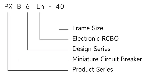
Type designation
Tripping curves
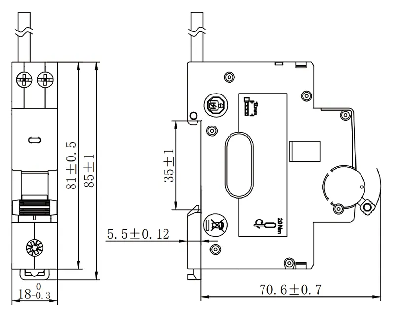
Dimensions(mm)