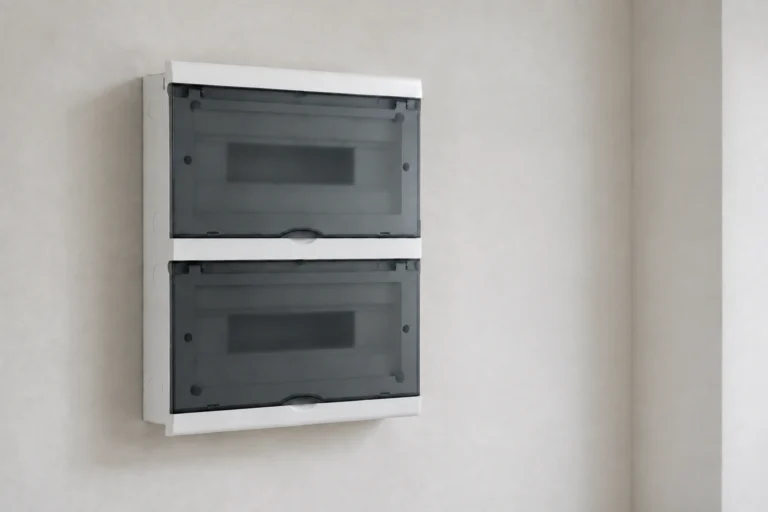
When project engineer Maya Chen in Houston encountered a late design change, she selected replacement boxes from nominal outside dimensions. After the electricians added conductors, splices, devices, and internal clamps, wiring rapidly became crowded and several covers would not seat without pressure. The boxes were not defective. The specification had ignored usable volume, conductor allowances, connector intrusion, and placement-driven cable routing.
Summary: No single box size is standard for every installation. For device and outlet boxes, NEC 314.16 uses volume allowances; for pull and junction boxes containing 4 AWG or larger conductors, NEC 314.28 uses raceway-based dimensions such as 8× the largest raceway for straight pulls. Specify internal volume, depth, entries, devices, and the locally adopted code—not outside dimensions alone.An electrical box can serve as an outlet, device, splice, or pull point, but those functions create different sizing constraints. Trade terms such as electric box, outlet box, j box, and junction boxes are not reliable specifications by themselves. Buyers need a dimensioned drawing, stated volume where relevant, material and enclosure information, entry arrangement, and confirmation against the destination market’s adopted rules.
What Electrical Box Dimensions Actually Control
External size, internal volume, and clear depth are different
Length, width, and depth on a catalog drawing may describe the outside envelope. Wall thickness, ribs, mounting bosses, knockouts, glands, clamps, and the cover reduce usable space. A nominal 100 mm-deep box therefore does not guarantee 100 mm of clear wiring depth. Procurement drawings should distinguish external dimensions, internal clear dimensions, published volume, opening size, and any component projecting into the enclosure.
Depth matters because conductors must bend without damage, devices and terminals extend behind the face, and connectors occupy the entry zone. NEC 300.14 also requires at least 150 mm (6 in.) of free conductor at outlet, junction, and switch points for splices or terminations. When the box opening is less than 200 mm (8 in.) in any dimension, each conductor must be long enough to extend at least 75 mm (3 in.) outside the opening. These free-length rules do not replace box-fill calculations, but they make shallow, congested layouts harder to assemble and service.
There is no universal standard size
The phrase standard junction box size can refer to a familiar trade format in one country, a supplier’s series, or a project standard. It does not establish one globally interchangeable size. Device patterns, metric and imperial entries, cover geometry, mounting centers, conductor systems, and local rules vary. Even boxes with the same outside width can have different volumes and entry clearances.
IEC 60670-1 covers general requirements for boxes and enclosures for electrical accessories used in household and similar fixed electrical installations. It is a product-standard framework, not a table that makes every compliant box the same size. Likewise, a size commonly sold in North America should not be assumed to fit IEC-market accessories or project-specific glands.
How Box-Fill Logic Changes the Required Size
For outlet and device boxes covered by NEC 314.16, sizing begins with the box’s marked or code-recognized volume and the volume allowances assigned to conductors and equipment. Each insulated conductor that originates outside and terminates or is spliced inside generally counts as one conductor allowance; a conductor passing through without splice or termination also counts. Internal clamps, support fittings, device yokes, and grounding or bonding conductors receive additional treatment under the adopted edition.
Table 314.16(B) assigns, for example, 2.00 in³ per 14 AWG conductor, 2.25 in³ per 12 AWG conductor, and 2.50 in³ per 10 AWG conductor. A device yoke counts as two conductor volumes based on the largest conductor connected to that yoke. Because grounding-conductor treatment has changed between NEC editions, calculations and quotations should identify the edition adopted by the authority having jurisdiction (AHJ).
Illustrative comparison of dimension and sizing methods
Method
Input
What it answers
Key limitation
Nominal external size
Overall length, width, depth
Will the enclosure fit the allotted space?
Does not reveal wall, boss, gland, or cover intrusion
Usable internal volume
Marked or verified volume and clear geometry
Is there physical space for wiring and components?
Volume alone does not prove code fill or bend clearance
Must use the locally adopted edition and actual configuration
Large-raceway pull sizing
Pull type and raceway trade sizes
What minimum pull-direction dimensions follow NEC 314.28?
Applies to conductors 4 AWG and larger; layout still matters
The practical depth of electrical box installations must also accommodate wiring choreography. A calculated volume can pass while a device still becomes difficult to seat because stiff conductors, splicing connectors, terminal blocks, or cable glands concentrate in one plane. A useful RFQ therefore requests both compliance data and a drawing showing clear depth behind the installed cover or device.
What can go wrong when the box is too small?
Overcrowding can produce sharp conductor bends, damaged insulation, stressed terminations, trapped wires at the cover, poor heat dissipation around components, and slow inspection or maintenance. Installers may be tempted to force the cover, shorten serviceable conductor length, or improvise an extension.
How Pull Geometry and Receptacle Placement Affect Sizing
Large conductors use a raceway-based pull-box rule
NEC 314.28 applies to pull and junction boxes with conductors 4 AWG and larger. For a straight pull, the box length in the direction of pull must be at least eight times the trade size of the largest raceway. An illustrative 2-inch raceway therefore requires at least 16 inches in the pull direction, subject to all other applicable conditions.
For angle pulls or U pulls, the distance from each raceway entry to the opposite wall must be at least six times the trade size of the largest raceway in the row, plus the sum of the trade sizes of the other raceways in that row on the same wall. For example, a 2-inch raceway and a 1.5-inch raceway in the same row produce an illustrative minimum of 13.5 inches from the 2-inch entry to the opposite wall: 6 × 2 + 1.5. Raceway spacing, fittings, conductor bending space, and the adopted edition still require review.
The NEC 6/12 rule sets placement, not box volume
NEC 210.52’s commonly described 6/12 rule addresses receptacle placement in specified dwelling-unit wall spaces: receptacles are arranged so that no point measured horizontally along the floor line is more than 6 ft from a receptacle, which commonly results in no more than 12 ft between adjacent receptacles. It does not determine box volume, conductor allowance, or pull-box length.
Placement can nevertheless change sizing indirectly. More outlets, longer routes, feed-through wiring, or a different device layout can increase the number of conductors and yokes in particular electrical boxes. The designer should establish outlet locations under 210.52, free conductor length under 300.14, box fill under 314.16, and large-conductor pull geometry under 314.28 as separate checks.
Bonding, corrosion environment, knockout and device compatibility
Nonmetallic outlet/device box
Application-dependent
Devices and branch wiring
Corrosion resistance and electrical insulation
Temperature, support method, cable entries, and local listing requirements
Pull or junction enclosure
Driven by pull geometry
Raceway transitions and conductor pulling
Accessible routing and maintenance point
314.28 dimensions, bending space, entry rows, and cover access
Cabinet distribution connection box
Driven by terminals and routing
Centralized wire splitting inside panels or control equipment
Organized connection architecture
Terminal ratings, internal layout, clearances, documentation, and enclosure context
Weather-exposed enclosure
Must allow seals and glands
Outdoor or wash-down locations
Environmental protection when correctly specified
IP/NEMA claim scope, drainage, UV, corrosion, and installed entry system
Standards and Compliance Checks for Procurement
NEC/NFPA 70 is an installation code. Articles 210.52, 300.14, 314.16, and 314.28 answer different placement, conductor-length, fill, and pull-space questions. The applicable edition is the one adopted by the project jurisdiction, with interpretation and approval by the AHJ. A vendor’s dimensional drawing cannot by itself demonstrate that a completed installation complies.
IEC 60670-1 addresses general requirements for boxes and enclosures for electrical accessories in household and similar fixed installations. IEC 60529 defines the IP Code and associated ingress-protection test classification. An IP rating concerns tested protection against access, solid objects, and water under stated conditions; it is not a blanket certification of electrical performance or suitability after installers add unverified holes or glands.
UL 514A covers metallic outlet boxes, while UL 514C covers nonmetallic outlet boxes, flush-device boxes, and covers within their stated scopes. Citing a standard is not the same as proving that a particular model is certified or listed. Buyers should request the exact model’s current certification evidence from an acceptable certification body when the project requires it, then verify markings, accessories, and installation conditions.
Destination-market differences affect commercial risk. A dimensionally suitable box may still be rejected because its device interface, materials, markings, environmental rating, or certification path does not match the specification. RFQs should separate mandatory compliance evidence from optional test reports and avoid phrases such as “UL compliant” or “IP certified” unless the claim is supported for the exact supplied configuration.
Selection Guide for a Clear, Comparable RFQ
Define the function. State whether the unit is an outlet box, splice box, pull box, cabinet connection box, or environmental enclosure; a familiar junction box label is not enough.
Submit the wiring schedule. Include conductor count and gauge, grounding method, devices, yokes, terminals, clamps, splice connectors, raceway sizes, and pull direction.
Request controlled drawings. Ask for electrical box dimensions that separate external size, opening, clear internal depth, usable volume, mounting centers, entry positions, cover intrusion, and tolerances.
Define the environment and market. State indoor or outdoor location, temperature and corrosion conditions, ingress requirement, destination, adopted code edition, certification requirement, and AHJ expectations. For exposed installations, review this outdoor junction-box selection guide.
Review a populated layout. Use the intended terminals, glands, conductors, and cover before volume production. Confirm service access and label every hypothetical calculation as illustrative.
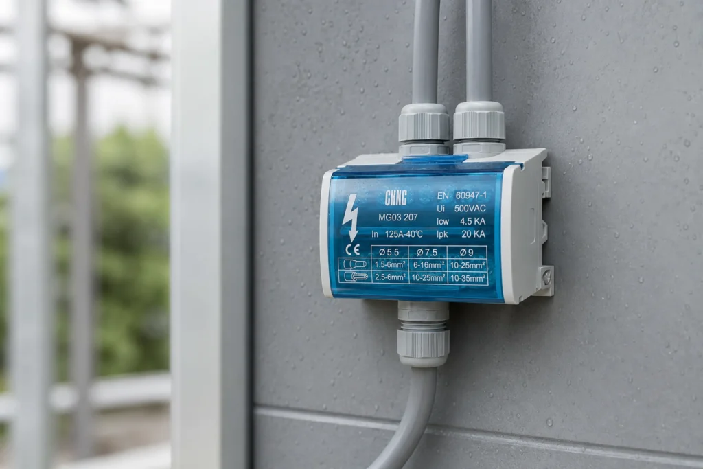
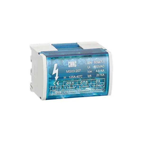
At this decision stage, CHAC Electric can be considered as a China-based B2B low-voltage electrical equipment manufacturer. Its public CQMG03 page describes a distribution junction-box solution intended to support tidy cabinet wiring and centralized wire splitting for low-voltage distribution panels and industrial control equipment. Buyers should still submit project drawings, ratings, quantities, and destination requirements for model-level review.
There is no universal width. Many North American three-gang device boxes are roughly 5.5 to 6 inches wide externally, but material, wall type, device spacing, and manufacturer geometry vary. Use the exact model’s outside width, opening, mounting-center, and volume drawing rather than treating this range as a specification.
How to Size Junction Box?
First identify the conductors and function. Use NEC 314.16 volume allowances for applicable outlet/device boxes and NEC 314.28 raceway-based dimensions when 4 AWG or larger conductors are pulled through junction or pull boxes. Then check clear depth, fittings, access, environment, and the local code edition with the AHJ.
How Much Wire to Leave in Electrical Box?
NEC 300.14 generally requires at least 6 inches of free conductor measured from where it emerges from the raceway or cable sheath. If the box opening is less than 8 inches in any dimension, each conductor must extend at least 3 inches outside the opening. Verify the locally adopted NEC edition and do not confuse this free-length rule with the 6/12 receptacle-spacing rule.
Does a Deeper Box Always Solve Box Fill?
No. More depth may increase volume and improve wiring access, but compliance depends on the box’s recognized volume and the complete allowance calculation. A deeper unit can still fail if glands, devices, terminals, or pull geometry create conflicts.
Can the Same Box Be Used Indoors and Outdoors?
Only when the exact box, cover, seals, entries, and installed configuration are suitable for both environments. Check the required ingress or enclosure rating, corrosion and UV exposure, drainage, temperature, and destination-market approval; modifying entries can affect the claimed protection.
The memorable principle is simple: size the wiring space from what must happen inside it, not from what the enclosure looks like outside.
For cabinet projects requiring organized centralized wire splitting, review the CQMG03 Series Distribution Junction Box Connection Solutions. Contact CHAC Electric with your conductor schedule, panel layout, destination market, quantities, and required documentation for a project-specific discussion.