A feeder replacement can carry the same ampere rating as the original breaker and still need a new protection study. The frame, fitted trip unit, overload setting, short-circuit performance, and accessories are separate selection decisions. Treating them as one rating can leave a cable inadequately protected or invalidate an upstream/downstream coordination claim. For a CQM6 distribution design, the useful question is not simply which breaker has enough current capacity, but which exact configuration protects the installed circuit under its actual operating conditions.
The short answer is to select by circuit duty, system voltage, prospective short-circuit current, trip behavior, pole arrangement, accessories, and coordination evidence, not current alone. IEC 60947-2:2024 covers circuit-breakers up to 1,000 V AC or 1,500 V DC; those scope limits are not CQM6 product ratings. The CQM6 pages describe AC 400/415 V configurations whose current values and breaking classes depend on the exact model. Begin with the fault-current and cable calculations, confirm the ordered configuration’s Icu and Ics, and obtain applicable trip curves and pairing data before releasing the panel.
Why can the same ampere rating mean different protection?
A molded case circuit breaker combines switching contacts, an operating mechanism, and a trip system inside an insulating molded enclosure. Under overload or short-circuit conditions, the trip system releases the mechanism so the contacts open. That basic description does not establish whether one device fits an incomer, feeder, motor circuit, or final branch.
Frame rating and trip rating answer different questions. The frame rating, commonly identified as Inm, describes the frame size; the rated current or adjustable pickup relates to the trip unit fitted to that frame. A larger frame with a lower setting is not automatically interchangeable with a smaller frame at the same nominal current because dimensions, terminals, accessories, trip curves, and short-circuit performance can differ.
Does a larger frame provide spare capacity without changing cable protection?
Not by itself. Schneider Electric’s Fundamental characteristics of a circuit-breaker distinguishes frame size, the fitted trip unit’s rated current In, and overload pickup Ir. It also ties rated current to the manufacturer’s stated ambient conditions. A frame may accommodate different trip-unit ratings, but that does not establish that a particular CQM6 trip unit is interchangeable or that every setting within a family is available.
For an adjustable configuration, record both the trip-unit rating and the approved Ir setting on the circuit schedule. Check the setting against design load and the conductor’s permissible current after installation corrections. Reserve frame capacity is not permission to raise Ir later: a load increase requires a fresh check of cable capacity, terminals, enclosure conditions, and coordination. For a fixed configuration, select the published rating and curve that satisfy those checks rather than treating the frame marking as the protection setting. Schneider’s numerical examples describe its own devices and must not be used as CQM6 adjustment or derating data.
Short-circuit duty is separate again. The prospective fault current is the current the installation could deliver at the breaker location. Icu is the rated ultimate short-circuit breaking capacity, while Ics is the rated service short-circuit breaking capacity under the standard’s defined test sequence. The designer should compare the calculated fault level with the detailed values for the exact frame and ordered model at the applicable voltage; an overview maximum or breaking class is not a blanket rating for every configuration.
Which CQM6 configuration fits the circuit?
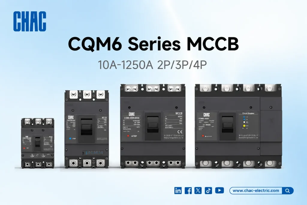
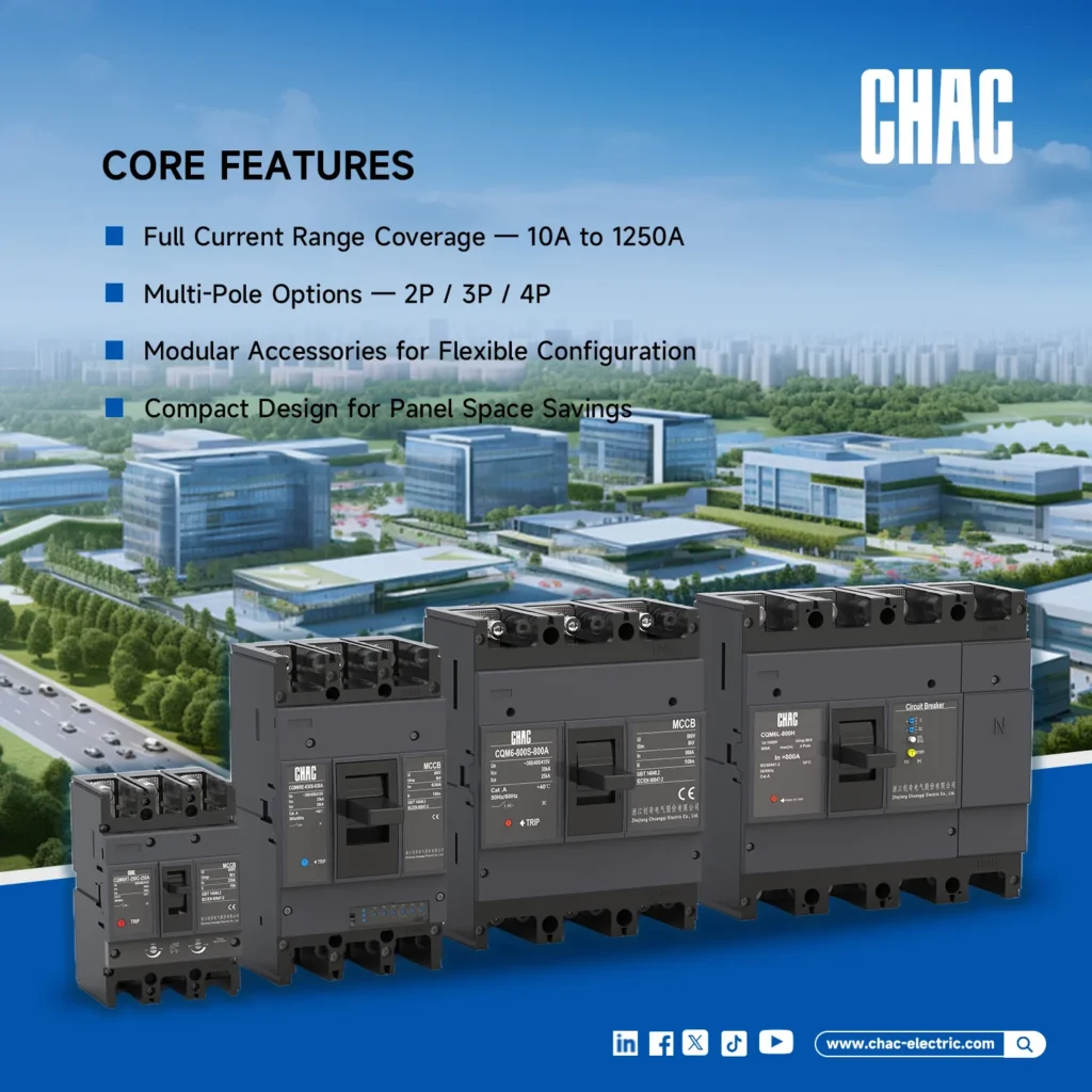
The product pages distinguish three approaches. The standard CQM6 molded case circuit breaker presents 10-1250 A, 2P/3P/4P, AC 400/415 V, and thermal-magnetic protection, while the CQM6RT adjustable thermal-magnetic MCCB presents 63-800 A, 3P/4P, AC 400/415 V, with adjustable thermal Ir and magnetic Im. The CQM6E presents 3P/4P, AC 400/415 V, and adjustable electronic L-S-I-G protection; because its overview range and detailed rating table are not fully aligned, no single CQM6E current range should govern procurement. These are published family descriptions, not proof of availability for every combination. Obtain the detailed ordered-model data to confirm current, breaking class, Icu/Ics, poles, and protection functions for the exact frame.
| Application duty | First engineering question | Potential family direction | Evidence still required |
|---|---|---|---|
| Main incomer | What fault level and continuity objective exist at the bus? | Standard, adjustable thermal-magnetic, or electronic option depending on study | Exact Icu/Ics, trip curve, upstream source data, downstream coordination table, poles, isolation method |
| Distribution feeder | Can the feeder cable be protected while preserving downstream discrimination? | Fixed protection for stable duties; adjustable option where the study needs setting flexibility | Cable calculation, settings, time-current study, enclosure derating, terminal data |
| Motor circuit | Which device provides overload, short-circuit, switching, and phase-related functions? | A product configuration published for motor protection, integrated with the chosen control architecture | Motor starting profile, contactor/overload or motor-protection device data, coordination type, test evidence |
| Branch circuit | Does the load require MCCB fault duty or accessories rather than a compact final-circuit device? | Use an MCCB only when the duty and panel architecture justify it | Load calculation, conductor ampacity, local rules, fault level, space, terminals, maintenance plan |
How do protection features affect cost and maintenance?
Good MCCB selection considers the engineering effort after purchase. Fixed protection can reduce setting decisions in a stable design. Adjustable thermal-magnetic protection can help align overload and instantaneous response with a feeder or motor study. Electronic protection can add more setting functions for projects that need long-time, short-time, instantaneous, or ground-fault functions, but only the functions and adjustment ranges documented for the ordered device should enter the design.
| Decision factor | Fixed thermal-magnetic | Adjustable thermal-magnetic | Electronic adjustable |
|---|---|---|---|
| Setting flexibility | Lower; suitable where published curve fits the duty | Ir and Im adjustment on the listed CQM6RT configurations | L-S-I-G adjustment on the listed CQM6E configurations |
| Coordination work | Compare the published curve and pairing data | Document field settings and tolerances | Document every enabled function, threshold, and delay |
| Accessory/control review | Confirm the exact frame, mounting arrangement, accessory type, and control voltage; never transfer an accessory assumption from another frame or model | ||
| Unit-cost tendency | Generally fewer setting features | Added adjustment capability | Added protection and setting capability; no universal price relationship is assumed |
| Maintenance exposure | Fewer settings to record | Settings require commissioning control | More settings require disciplined records and change management |
| TCO implication | Evaluate device cost plus engineering, validation, panel changes, commissioning, spares, and the consequence of unnecessary upstream trips | ||
Illustrative TCO method: compare the shortlisted options as device and accessory cost + study and documentation hours + commissioning time + expected change cost + downtime exposure. This is a decision structure, not a savings claim; project values must come from the buyer’s quotations, labor rates, and risk model.
What is the difference between selectivity and backup protection?
Selective coordination aims for the protective device nearest a fault to open while upstream devices remain closed, within the documented limits. Schneider Electric’s Selective Coordination with Molded Case Circuit Breakers explains why time-current curves alone can be insufficient in the instantaneous region and why manufacturers publish short-circuit coordination tables for specific breaker pairs.
Backup protection, also called cascading in some markets, is a different concept. It uses a verified upstream device’s current-limiting behavior to support a downstream combination at a stated fault level. Backup does not automatically provide selectivity, and selectivity does not automatically raise a downstream device’s breaking capacity. Neither relationship should be inferred from brand, frame size, or matching ampere ratings; use tested or manufacturer-declared combination data applicable to the exact devices, voltage, and fault level.
What evidence is needed to approve coordination?
- Single-line diagram, system voltage and frequency, earthing arrangement, and calculated prospective short-circuit current at each relevant point.
- Exact breaker order codes, frame ratings, trip ratings, poles, protection functions, and proposed settings.
- Published Icu and Ics values at the project voltage, plus any short-time withstand data used in the study.
- Time-current curves with tolerances and a manufacturer coordination or backup table for the exact upstream/downstream pair.
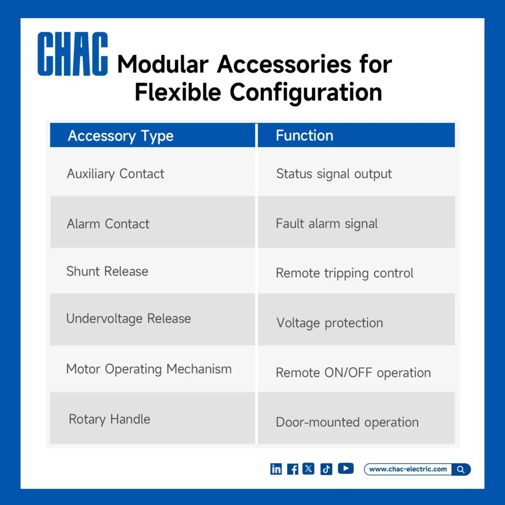
- Accessory schedule identifying shunt release, undervoltage release, auxiliary/alarm contacts, operating mechanism, mounting form, and required control voltage.
- Terminal, conductor, torque, clearance, ambient, altitude, and enclosure information for the ordered configuration.
- Market-required declarations, test reports, drawings, instructions, and traceability records; a standard printed on a page is not by itself a complete approval package.
What does IEC 60947-2 cover, and what does a CE mark mean?
IEC 60947-2:2024, edition 6.0, applies to circuit-breakers whose main contacts connect to circuits not exceeding 1,000 V AC or 1,500 V DC and intended for operation by instructed or skilled persons. The IEC page identifies technical revisions that include individual-pole breaking-capacity testing under phase-to-neutral AC voltage, additional ground-fault release tests, dielectric tests in the tripped position, and changes to power-loss measurement. These are standard-scope and test-method facts, not proof that every CQM6 configuration has undergone every optional assessment.
The European Commission’s CE marking guidance adds a separate documentation distinction: the mark is the manufacturer’s declaration that applicable legal requirements are met, not approval of safety by the EU or another authority. For an EEA order, request the EU declaration of conformity identifying the supplied product and applicable legislation, and check that the configuration matches the supporting documentation. A CE logo does not establish breaker-pair selectivity, panel acceptance, or a particular breaking rating. No CQM6 declaration of conformity has been assessed here.
Commercially, an unsupported compliance statement can delay panel acceptance, force substitutions, or create a documentation gap between the quotation and delivered configuration. The destination market, intended use, panel standard, installation code, and buyer specification determine which evidence is required. IEC 60947-2 is not a substitute for the local installation rules, a project fault study, or a panel-level verification.
How can a fault study become an unambiguous purchase order?
- Define circuit duty, design current, conductor limits, voltage, poles, load behavior, and the destination rules.
- Calculate the prospective fault current at the installation point; shortlist only exact configurations with suitable published breaking data.
- Model overload and short-circuit behavior using current manufacturer curves, tolerances, and coordination or backup tables.
- Freeze accessories and their control voltages before the panel layout is released, then verify mounting, terminals, wiring space, and operating handle arrangement.
- Attach the evidence checklist to the purchase specification so quotations can be compared on the same technical basis.
Write the accessory’s required control supply separately from the breaker’s main-circuit voltage: AC or DC, voltage, and frequency where applicable. If a breaker or frame is substituted, reopen the accessory and wiring review as well as the protection study. Require confirmation of the exact accessory part number and operating requirements; matching the family’s name is not evidence of fit or correct control operation.
CHAC’s MCCB range gives panel builders and OEM buyers a starting point for comparing fixed, adjustable thermal-magnetic, and electronic options. The final choice should be tied to an approved study and the documentation for the exact ordered configuration.
What else should engineers ask when selecting an MCCB?
What is the 80% rule for circuit breakers?
The phrase usually refers to North American continuous-load sizing discussions, not a universal MCCB limit. It should not be applied to CQM6 from an IEC rating alone. Confirm the adopted installation code, load classification, equipment listing, conductor sizing, and enclosure conditions with the project designer.
How does a molded case circuit breaker work?
Current passes through the breaker’s contacts and sensing system. When the trip unit detects an overload or short-circuit condition beyond its defined curve or settings, it releases the mechanism and opens the contacts. The exact thermal, magnetic, electronic, delay, and ground-fault functions depend on the ordered model and settings.
How do you calculate the breaking capacity of a circuit breaker?
You do not calculate a breaker’s breaking capacity from load current. A short-circuit study calculates the prospective fault current at the installation point; the designer then checks that value against the manufacturer’s Icu/Ics data at the correct voltage, poles, frame, and configuration. Apply any required panel-level and coordination rules as separate checks.
What is the 125% rule in electrical?
It is a shorthand associated with some North American sizing discussions, not a universal multiplier for every load or an IEC product specification. This article does not establish a project-specific NEC calculation. Use the adopted code’s provisions for the actual circuit, loads, conductors, and listed equipment instead of sizing a CQM6 order from the percentage alone.
How do you verify MCCB selectivity or cascading?
Use the exact upstream and downstream part numbers, system voltage, prospective fault current, settings, time-current curves, and manufacturer tables. A curve study can support overload-region selectivity, but short-circuit behavior may require tested pairing data. Record whether the evidence demonstrates selectivity, backup/cascading, or both; do not use the terms interchangeably.
Is an MCCB in the OFF position automatically suitable for isolation?
No. Schneider Electric’s Fundamental characteristics of a circuit-breaker explains that suitability for isolation depends on meeting the relevant disconnector requirements at the rated voltage and carrying the appropriate marking. Verify that marking and the exact CQM6 documentation rather than assuming every switching device is an isolator. Isolation suitability also does not replace the site’s safe isolation and lockout procedure.
Which sources explain these selection boundaries?
- IEC 60947-2:2024 – Low-voltage switchgear and controlgear, Part 2: Circuit-breakers
- Fundamental characteristics of a circuit-breaker – Schneider Electric Electrical Installation Guide, updated August 5, 2026; manufacturer examples are not CQM6 specifications.
- Selective Coordination with Molded Case Circuit Breakers – Schneider Electric, October 6, 2016; explanatory guidance, not CHAC pairing evidence.
- CE marking – European Commission; explains manufacturer obligations, not a product-specific conformity assessment.