
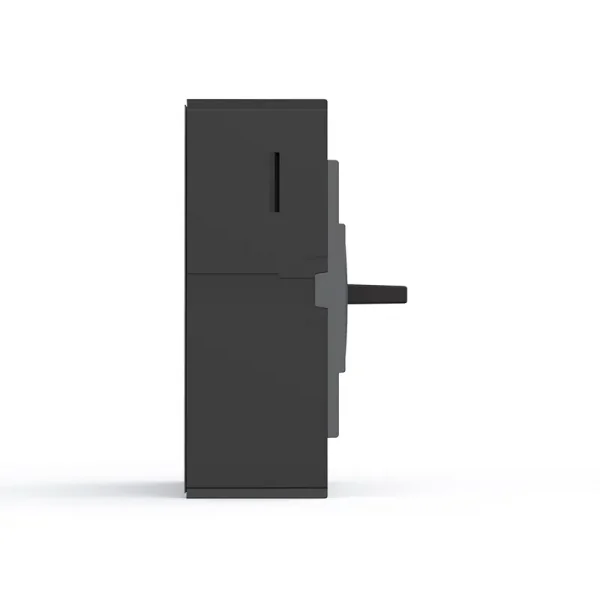



CQM6L Leakage-Integrated MCCB OEM/ODM Manufacturer
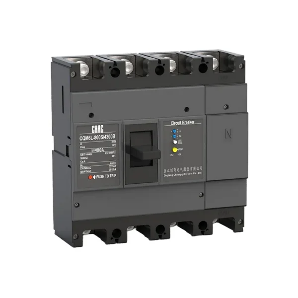
The CQM6L MCCB provides overload, short circuit and adjustable earth-leakage protection within its published 10–1250A frame range; verify ordered In range. Specification should follow the system voltage, load, conductor coordination, prospective fault current and applicable rules—not the ampere value alone.
Product Overview
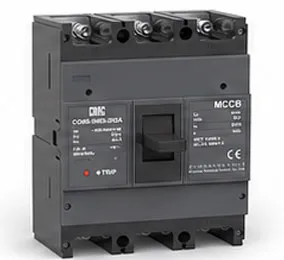
CQM6L is a earth leakage circuit breaker for AC 400/415V distribution and protection applications. Its published range covers 10–1250A frame range; verify ordered In with 3P / 4P options. Selection depends on the complete power-system design, including fault level, coordination, conductor ampacity, enclosure conditions and local rules.
The saved model record lists IEC/EN 60947 and GB/T 14048 references listed on the page as the applicable standard reference. No certification claim is added beyond the model record.
Key Features
Typical Applications
Typical applications include distribution and motor circuits where an MCCB and residual-current function are specified together. These are evaluation contexts rather than universal approvals. Confirm the exact frame, voltage, breaking duty, trip unit, accessories and installation method before specification.
Applications and Selection Guide
Use the verified CQM6L values below to create a shortlist, then validate the complete circuit. An MCCB rating does not replace conductor calculations, fault-current analysis, coordination review or local installation requirements.
| Selection point | CQM6L reference | What the project must confirm |
|---|---|---|
| Rated current | 10–1250A frame range; verify ordered In | Design current, conductor ampacity, installation method, temperature and grouping |
| Voltage | AC 400/415V | Supply system and equipment rating |
| Poles | 3P / 4P | Live conductors and neutral treatment |
| Trip / protection | thermal-magnetic trip | Load profile, fault response and coordination |
| Breaking capacity | C/S/M/H classes up to 75kA, according to frame and ordered configuration | Prospective short-circuit current at the installation point |
Overcurrent vs Earth-Leakage Protection
An MCCB's overcurrent function does not replace residual-current protection. Select leakage sensitivity, delay and waveform type from the verified model data and project rules.
Leakage Protection
Confirm Leakage Selection →
MCCB vs MCB
An MCCB is normally evaluated for higher current, fault duty or accessory flexibility; an MCB may be more suitable for compact final circuits.
Current & Fault Duty
Compare MCCB and MCB →
Icu vs Ics
The saved data for CQM6L lists C/S/M/H classes up to 75kA, according to frame and ordered configuration. Match the declared duty to the prospective short-circuit current and continuity objective.
Short-Circuit Study
Review Technical Support →
Pole and Neutral Arrangement
Published pole options are 3P / 4P. Confirm which conductors must be switched, protected and isolated together.
System Arrangement
View MCCB Range →
Ordering Guide
- State the exact model: CQM6L.
- Provide frame and rated current within the published range: 10–1250A frame range; verify ordered In.
- Confirm poles: 3P / 4P.
- Specify the trip unit or protection function: thermal-magnetic trip.
- Provide system voltage, frequency, application, expected fault level, destination market and quantity.
- List required accessories, terminals, documents and any approved OEM/ODM marking or packaging requirements.
Installation and Coordination Checks
- Use the exact model drawing and instructions; do not infer terminal positions, supply direction or accessory compatibility from another MCCB.
- Verify conductor material and cross-section against the circuit calculation, terminal data, temperature and grouping.
- Confirm Icu/Ics or DC fault duty, upstream/downstream coordination, enclosure conditions, altitude and clearances.
- Installation, isolation, testing and maintenance must be performed by qualified personnel under applicable rules.
Accessory List
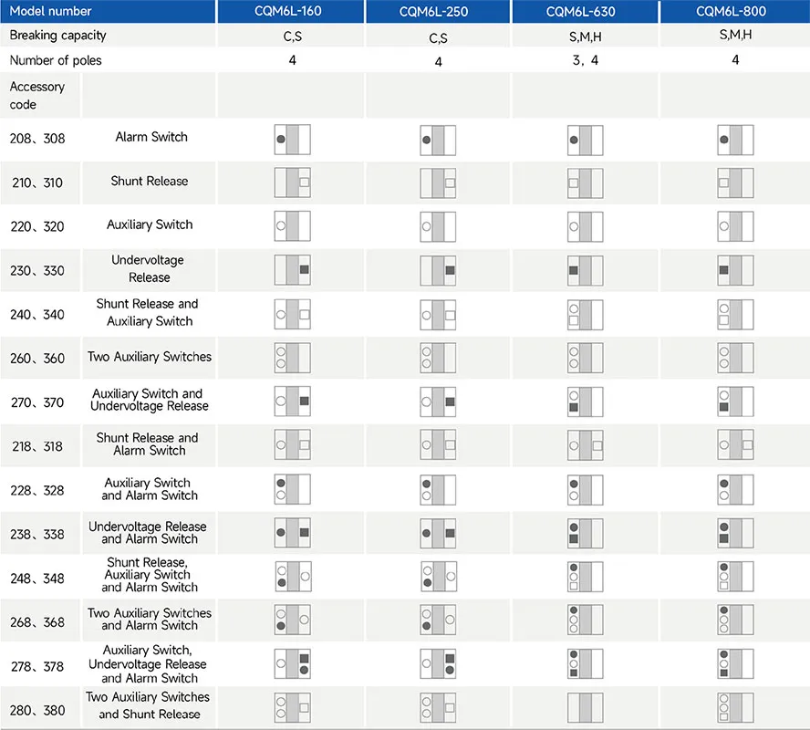
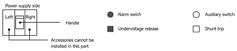
Selection Guide

| Product code ① | Shell frame grade ② | Breaking capacity ③ | Operating method ④ | The number of poles ⑤ | ||||
| CQM6L | 160 | C | P | 4 | ||||
| Molded case circuit breaker |
C | S | M | H | P:Motorized operation Z:Turning handle W.Direct operation |
3-pole 4-pole |
||
| 160 | 160 | 25/18 | 35/25 | / | / | |||
| 250 | 250 | 25/18 | 35/25 | / | / | |||
| 630 | 630 | / | 35/25 | 50/35 | 75/75 | |||
| 800 | 800 | / | 35/25 | 50/35 | 75/75 | |||
| 1250 | 1250 | / | 35/25 | 50/35 | 75/75 | |||
| Decoupler method and internal accessories ⑥ | Rated current A ⑦ | Function ⑧ | Optional code for four-pole products ⑨ | Special code ⑩ | |
| 300 | 160A | 2 | A | I | |
| The first digit indicates the type of detent 2:Instantaneous detent only 3:Duplicate detent Note:The last two digits are the accessory designator(see accessory table). |
160 | 10,16,20,32,40,50,63,80,100,125,140,160 | 1:For power distribution 2:For motor protection |
A:N-pole is unprotected and cannot be combined B:N-pole is unprotected and can be combined C:N-pole is protected and can be combined D:N-pole is protected and cannot be combined |
I: Overload alarm non trip function |
| 250 | 100,125,140,160,180,200,225,250 | ||||
| 630 | 250,315,350,400,500,630 | ||||
| 800 | 500,630,700,800 | ||||
| Product code ⑪ | Breaking capacity ⑫ | ||||||
| L1 | Y1 | ||||||
| Fixed delay type | Quick three-step adjustable | Fixed delay type | Quick three-step adjustable | ||||
| L1:30 | L6:200 | L11:30,50,100 | Y1:0.1S | Y4:0.4S | Y7:0.7S | Y10:1.0S | Y13:0.45,1,2 |
| L2:50 | L7:300 | L12:30,100,200 | |||||
| L3:75 | L8:500 | L13:30,100,500 | Y2:0.2S | Y5:0.5S | Y8:0.8S | Y11:1.1S | Y14:1,2,3 |
| L4:100 | L9:500 | L14:100,300,500 | |||||
| L5:150 | L10:1000 | L15:100,300,500 | Y3:0.3S | Y6:0.6S | Y9:0.9S | Y12:1.2S | |
| L16:100,300,1000 | |||||||
| Accessory Voltage ⑬ | Motorized operating voltage ⑭ | Installation ⑮ | Whether to install a terminal block ⑯ | |||
| Q1 | D1 | Q | 2 | |||
| Undervoltage detent Q1:AC220V Q2:AC240V Q3:AC380V Q4:AC415V |
Shunt release F1:AC220V F2:AC380V F3:DC110V F4:DC24V |
Auxiliary alarm J1:AC125V J2:AC250V J3:DC125V J4:DC24V |
DC1 Electrical Operation D1:AC220V D2:AC230V D3:AC380V D4:AC400V |
DC3 Electrical Operation D5:AC230V D6:AC110V D7:DC220 D8:DC110 D9:AC110~240V D10:DC100~220V |
Q:Front of plate H:Rear of plate C:Inserted |
1:No installation 2:Installation |
| Note:When motorized operation is selected,please refer to the external accessories for the two voltages applicable for motorized operation. | ||||||
Main Technical Parameters
| Model number | CQM6L-160 | CQM6L-250 | ||||
| Rated current of frame level Inm(A) | 160 | 250 | ||||
| Number of poles | 4 | 4 | ||||
| Rated current In(A),at 40℃,50℃,55℃ | 10, 16, 20, 32, 40, 50, 63, 80,100, 125, 160 | 125,140,160,180,200,225,250 | ||||
| Rated operating voltage Ue(V),AC 50/60Hz | 400/415 | 400/415 | ||||
| Rated insulation voltage Ui (V) | 800 | 800 | ||||
| Rated impulse withstand voltage Uimp(KV) | 8 | 8 | ||||
| Breaking capacity designation | C | S | C | S | ||
| Short-circuit breaking capacity Icu/Ics(kA) | AC400/415V | 25/18 | 35/25 | 25/18 | 35/25 | |
| Selectivity category | A | A | A | A | ||
| Number of operating cycles(cycle) | ON | 6000 | 6000 | |||
| OFF | 10000 | 10000 | ||||
| Trip mechanisms and protection types | Magnetic trip | Power distribution protection | ● | ● | ● | ● |
| Motor protection | ● | ● | ● | ● | ||
| Thermal-magnetic trip | Power distribution protection | ● | ● | ● | ● | |
| Motor protection | ● | ● | ● | ● | ||
| Accessory | Auxiliary contacts | ● | ● | ● | ● | |
| Alarm contacts | ● | ● | ● | ● | ||
| Shunt disconnect | ● | ● | ● | ● | ||
| Undervoltage detent | ● | ● | ● | ● | ||
| Manual operating mechanism | ● | ● | ● | ● | ||
| Motorized operating mechanism | ● | ● | ● | ● | ||
| Backplane wiring | ● | ● | ● | ● | ||
| Inserted | ● | ● | ● | ● | ||
| Coupling plate | ● | ● | ● | ● | ||
| Partition between phases | ● | ● | ● | ● | ||
| Derivative products | Dedicated for prepayment electric meters | ● | ● | ● | ● | |
| Overload alarm without trip | ● | ● | ● | ● | ||
| Overall dimensions (mm) (a-b-c-ca) | 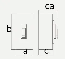 |
4 P | 120-155-70-94 | 140-165-70-96 | ||
Note:● for optional accessories;”-“for no optional accessories.
| Model number | CQM6L-630 | CQM6L-800 | ||||||
| Rated current of frame level Inm(A) | 630 | 800 | ||||||
| Number of poles | 3, 4 | 4 | ||||||
| Rated current In(A),at 40℃,50℃,55℃ | 250, 315, 350, 400, 500, 630 | 500,630,700,800 | ||||||
| Rated operating voltage Ue(V),AC 50/60Hz | 400/415 | 400/415 | ||||||
| Rated insulation voltage Ui (V) | 800 | 800 | ||||||
| Rated impulse withstand voltage Uimp(KV) | 8 | 8 | ||||||
| Breaking capacity designation | S | M | H | S | M | H | ||
| Short-circuit breaking capacity Icu/Ics(kA) | AC400/415V | 35/25 | 50/35 | 75/75 | 35/25 | 50/35 | 75/75 | |
| Selectivity category | A | A | A | A | A | A | ||
| Number of operating cycles(cycle) | ON | 3000 | 3000 | |||||
| OFF | 8000 | 8000 | ||||||
| Trip mechanisms and protection types |
Magnetic trip | Power distribution protection | ● | ● | ● | ● | ● | ● |
| Motor protection | ● | ● | ● | ● | ● | ● | ||
| Thermal-magnetic trip | Power distribution protection | ● | ● | ● | ● | ● | ● | |
| Motor protection | ● | ● | ● | ● | ● | ● | ||
| Accessory | Auxiliary contacts | ● | ● | ● | ● | ● | ● | |
| Alarm contacts | ● | ● | ● | ● | ● | ● | ||
| Shunt disconnect | ● | ● | ● | ● | ● | ● | ||
| Undervoltage detent | ● | ● | ● | ● | ● | ● | ||
| Manual operating mechanism | ● | ● | ● | ● | ● | ● | ||
| Motorized operating mechanism | ● | ● | ● | ● | ● | ● | ||
| Backplane wiring | ● | ● | ● | ● | ● | ● | ||
| Inserted | ● | ● | ● | ● | ● | ● | ||
| Coupling plate | ● | ● | ● | ● | ● | ● | ||
| Partition between phases | ● | ● | ● | ● | ● | ● | ||
| Derivative products | Dedicated for prepayment electric meters | ● | ● | ● | ● | ● | ● | |
| Overload alarm without trip | ● | ● | ● | ● | ● | ● | ||
| Overall dimensions (mm) (a-b-c-ca) |
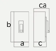 |
4 P | 185-257-105-155 | 280-275-105-155 | ||||
Note:● for optional accessories;”-“for no optional accessories.
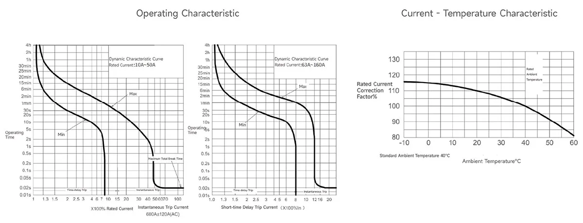
Operating Characteristics
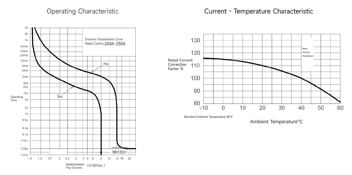
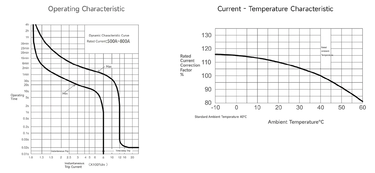
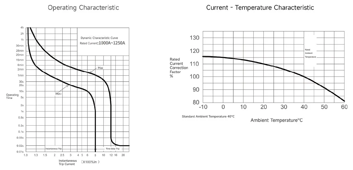
1.The inverse time operating characteristics of power distribution circuit breakers when all poles are energized simultaneously at anambient airtemperature of +40℃(with no humidity compensation)are shown in the following table:
| Test current designation | Setting current multiple | Conventional time | Initial state |
| In≤63 In>63 | |||
| Conventional non-tripping current | 1.05 | ≥1h ≥2h | Cool state |
| Conventional tripping current | 1.3 | <1h<2h | Hot state |
2.The inverse time action characteristics of circuit breakers for motor protection without humidity compensation when all poles areenergizedsimultaneously at an ambient air temperature of +40℃ are shown in the following table:
| Test current designation | Setting current multiple | Conventional time | Initial state |
| In≤800 | |||
| Conventional non-tripping current | 1.0 | ≥2h | Cool state |
| Conventional tripping current | 1.2 | <2h | Hot state |
3.Action characteristics under short-circuit condition:The short-circuit curent setting value of the instantaneous tripper of the circuit breaker forpower distribution is 10In
The short-circuit current setting value of the instaneous tripper of the circuit breaker for motorprotection is 12ln
The accuracy of the short-circuit curent setting value of the instantaneous tripper is 20% of the short-circuit currentsetting value.
CQM6L-125 Operating Characteristic Curve
CQM6L-250 Operating Characteristic Curve
CQM6L-630 Operating Characteristic Curve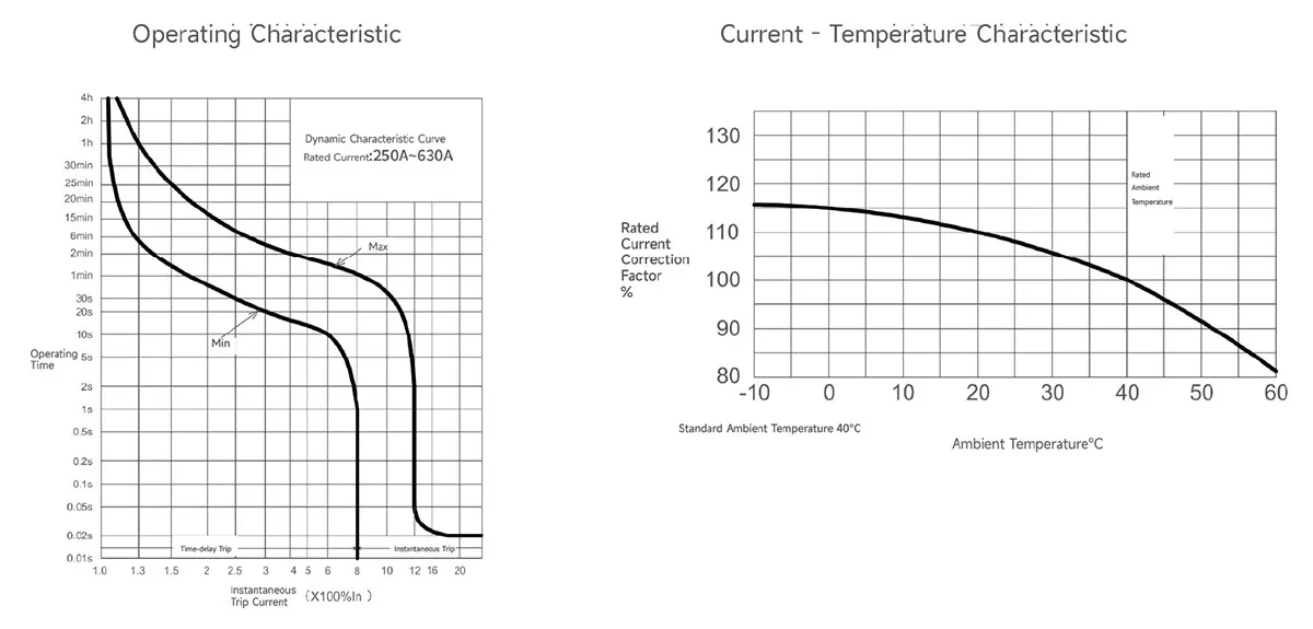
CQM6L-800 Operating Characteristic Curve
CQM6L-1250 Operating Characteristic Curve
Outline and Installation Dimensions(mm)
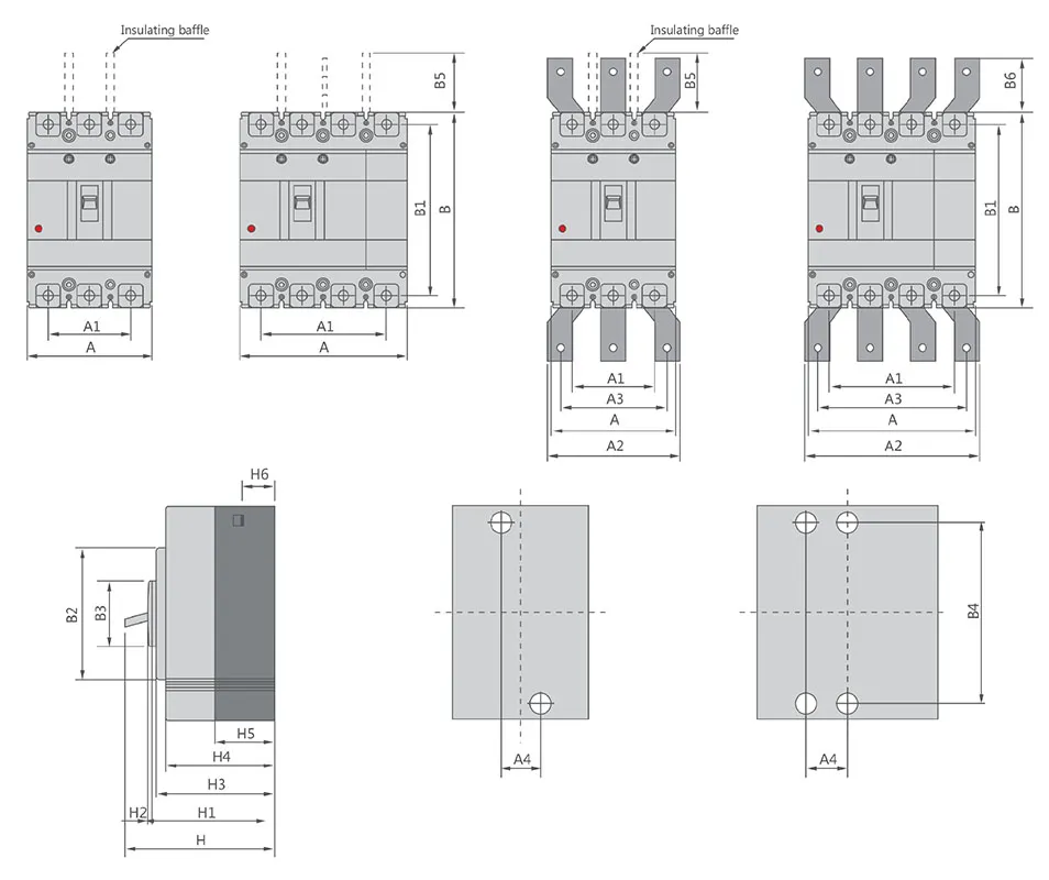
| Molded case circuit breaker |
Overall dimension | Installation dimensions |
Bolt | |||||||||||||||||||||
| A | A1 | A2 | A3 | B | B1 | B2 | B3 | B5 | B6 | H | H1 | H2 | H3 | H4 | H5 | H6 | A4 | B4 | ||||||
| 3P | 4P | 3P | 4P | 3P | 4P | 3P | 4P | |||||||||||||||||
| CQM6L-160 | – | 120 | – | 90 | – | – | – | – | 155 | 134 | 103 | 50 | 50 | – | 94 | 72 | 4 | 70 | 61 | 41 | 24 | 30 | 132 | M8 |
| CQM6L-250 | – | 140 | – | 105 | – | – | – | – | 165 | 144 | 103 | 50 | 100 | – | 96 | 72 | 4 | 70 | 61 | 46 | 24 | 35 | 126 | M8 |
| CQM6L-630 | – | 185 | – | 132 | – | 196 | – | 168 | 257 | 230 | 179 | 90 | 110 | 42 | 155 | 107 | 5 | 105 | 97 | 64 | 35 | 44 | 194 | M10 |
| CQM6L-800 | – | 280 | – | 210 | – | 250 | – | 210 | 275 | 243 | 192 | 90 | 110 | 87 | 155 | 107 | 5 | 104 | 97 | 65 | 24 | 70 | 242.5 | M12 |
Why Choose CHAC
With 30+ years of manufacturing experience, 1100+ employees, 100M+ poles
annual capacity and 90% automated production, CHAC provides stable production capacity and strict
quality control for global OEM/ODM customers. Our in-house manufacturing system supports long-term
cooperation for electrical brands, importers and distributors.

30+
YEARS EXPERIENCE
Specialized in low-voltage electrical manufacturing

1100+
EMPLOYEES
Professional team ensures stable quality and delivery

100M+
POLES ANNUAL CAPACITY
Large-scale production capacity to meet global demand

90%
AUTOMATED PRODUCTION
Advanced automation for high efficiency and consistency
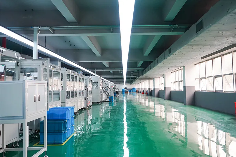
Automated Assembly Line

Testing Laboratory
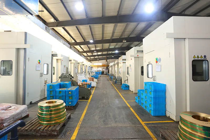
Injection & Stamping
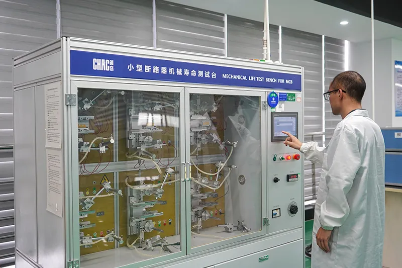
Quality Inspection



Strict quality control system ensures every product meets global standards.
What Can We Customize?
For CQM6L projects, CHAC can review private-label marking, packaging, approved appearance options, published 10–1250A frame range; verify ordered In electrical configurations and technical-document requirements. Requests outside the published range are subject to engineering evaluation, testing, minimum order quantity and project feasibility.

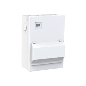
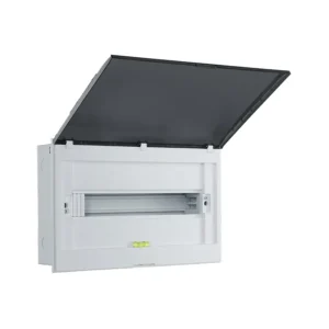
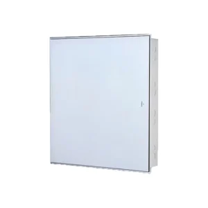
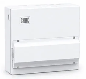
Enclosure
Design
Customized enclosure sizes, structures and installation details.

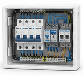
Internal
Configuration
Flexible internal layout and component arrangement options.

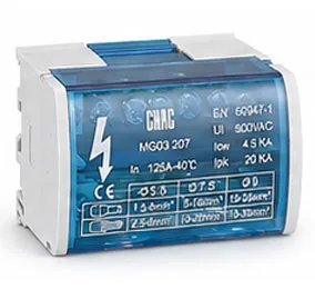
Branding &
Logo
Private label logos, nameplates and brand identification.

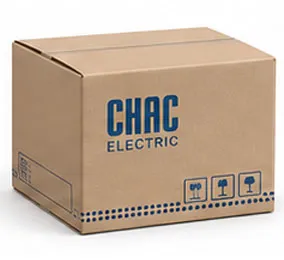
Packaging
Design
Custom cartons, labels, manuals and packaging solutions.

Electrical
Configuration
Tailored electrical setup based on application requirements.

Certification
Support
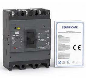
Support for target-market standards and compliance requirements.
Download
CQM6 Series Moulded Case Circuit Breaker
Complete product overview for low-voltage electrical components and product selection reference.
Need Technical Documents?
Contact us for datasheets, certificates, drawings, selection guidance or OEM/ODM project support.
CQM6L Product FAQ
What is the CQM6L MCCB used for?
The CQM6L is specified for overload, short circuit and adjustable earth-leakage protection in AC 400/415V systems within the published 10–1250A frame range; verify ordered In range. Suitability depends on the fault study, conductor coordination, enclosure and local rules.
How does residual-current protection work in the CQM6L?
The residual-current function monitors imbalance associated with earth leakage and trips at the selected sensitivity or delay. The waveform type, threshold, time delay, earthing arrangement and local rules must be confirmed for the exact configuration.
How do I choose the CQM6L rated current and poles?
Start with the design current and conductor calculation, then choose a published current within 10–1250A frame range; verify ordered In and poles from 3P / 4P. Neutral treatment, fault level, ambient conditions and coordination also need review.
What breaking capacity should I check on the CQM6L?
Use the declared C/S/M/H classes up to 75kA, according to frame and ordered configuration for the exact frame, voltage and configuration. The prospective short-circuit current at the installation point must be within the applicable duty; a larger ampere value alone is not a selection rule.
Can the CQM6L replace an MCB or an earth-leakage device?
An MCCB is not automatically a like-for-like replacement. The CQM6L provides overload, short circuit and adjustable earth-leakage protection; residual-current protection, DC interruption, adjustable settings and other functions must be confirmed separately from the project requirement.
How should the CQM6L be installed and tested?
Use only the exact model drawing, terminal identification and accessory instructions. A qualified person should verify isolation, conductor size, torque, clearances, settings, fault duty and functional tests before energising the circuit.
Confirm the Right CQM6L Configuration
Send the frame, rated current, poles, protection function, system voltage, expected fault level, destination market and quantity. CHAC will review the request against the published model range.