A relay and a contactor can appear interchangeable when a panel drawing shows only coil voltage and a contact-current rating. That comparison misses what the contacts must switch: a motor starting load, a compressor, a heater, or only a control signal. A device that carries the running current is not automatically suitable for making and breaking that load repeatedly. This guide separates power switching, control-circuit switching, and motor protection so panel builders can review the actual duty rather than choose by size or amperage alone.
The short answer is to use an AC contactor when its declared load and switching-duty ratings match the power circuit, and a control relay for logic, interlocking, or auxiliary switching within its contact ratings. There is no universal ampere threshold between them. For a motor starter, IEC 60947-4-1 is relevant to contactors, starters, and overload relays, but the selected manufacturer’s documentation must establish the actual ratings and permitted combinations. Check the power-contact duty, coil supply, overload function, and short-circuit protective device separately before approving the assembly.
What separates a contactor from a control relay?
A contactor is commonly used for repeated power-circuit switching. A control or auxiliary relay commonly switches interlocks, indicator branches, enable chains, and pilot devices. Both can use an electromagnetic coil; their intended contact duty, rather than that shared operating principle, determines whether they suit the application.
| Feature | AC contactor, typical use | Control relay, typical use |
|---|---|---|
| Primary duty | Power-circuit switching | Control-circuit switching |
| Contact rating to check | Declared load category, operational voltage, and making/breaking duty | Declared signal or pilot-load rating at the actual voltage |
| Arc handling | Load breaking within the manufacturer’s declared duty | Only the loads and switching conditions declared for that relay |
| Panel arrangement | May form a starter with overload and short-circuit protection | May provide logic or an interface to the contactor coil |
| Typical use | Motor starter, compressor, or appropriately rated lighting/heating branch | Logic, status, seal-in, or multi-circuit interlock |
A resistive-load current rating does not establish a motor-switching rating. If the contactor datasheet declares a category such as AC-3, use the rating at the project’s operational voltage and specified switching duty. Do not apply one category’s current rating to every load or assume that a lighting, capacitor, and motor application share the same requirements.
When does motor control require a contactor?
A magnetic contactor or motor starter is a common choice for repeated motor start/stop operation because the selected device must handle starting current, load interruption, and the required operating frequency. A small motor may instead use a relay with an explicit rating for that motor duty. Neither physical size nor a general-purpose contact-current label proves suitability.
| Application signal | Power-path choice | Possible relay role |
|---|---|---|
| Three-phase direct-on-line motor starter | Contactor or starter rated for the motor duty | Start/stop logic, not a presumed power-contact substitute |
| Motor remote start/stop from PLC | Rated contactor or starter | Coil interface if the PLC cannot drive the selected coil directly |
| Small fan or pump | Contactor or explicitly motor-rated relay, subject to application review | Power switching only within the documented motor rating |
| HVAC compressor | Device rated for the compressor’s specified starting and running duty | Thermostat logic and auxiliary signals |
| Status feedback to BMS | No additional power-switching device necessarily required | Auxiliary contact or standalone relay rated for the signal circuit |
If a branch already uses an MCCB or MCB for short-circuit protection, evaluate operational switching separately. A breaker’s protective rating alone does not establish suitability for the intended motor-cycling duty.
Where do relays still make sense in the same panel?
Relays can provide mode interlocks, additional control contacts, alarm aggregation, or an interface between control circuits. An auxiliary block on a contactor serves a similar signaling purpose in some arrangements. Its contacts are not interchangeable with the main power contacts: verify the auxiliary contact’s own load rating and function in the drawing.
| Panel function | Common device | Review point |
|---|---|---|
| Motor power switching | Contactor | Load type, operational voltage, and switching duty |
| Seal-in or latch logic | Control relay or suitable contactor auxiliary contact | Control-circuit rating and intended restart behavior |
| Alarm aggregation | Control relay | Required normally open and normally closed contacts |
| Remote indication | Auxiliary contact or relay | Signal-circuit rating and what the contact actually indicates |
How should the coil supply be checked separately from the load?
Coil voltage specifies the control interface, not the voltage or current that the main contacts may switch. A contactor with an AC power-circuit rating does not necessarily have an AC coil; order the exact coil option documented by the manufacturer. Confirm supply type, voltage, frequency where applicable, and permitted supply variation independently of the motor rating.
For a PLC-controlled starter, compare the output’s capabilities with the coil’s documented pickup and holding requirements. Include any interposing relay and suppression accessory in that check rather than assuming a voltage match makes direct connection acceptable. This separates two different problems: contacts unsuitable for the motor load, and a correctly selected contactor that the control supply cannot operate reliably.
How do overload and auxiliary devices change the choice?
For a motor branch, the AC contactor vs relay decision addresses switching, not the whole protection scheme. Define which component performs each function before selecting the assembly.
| Component | Role in motor branch | Selection note |
|---|---|---|
| Contactor | Switches motor power on command | Motor duty, coil option, poles, and auxiliaries |
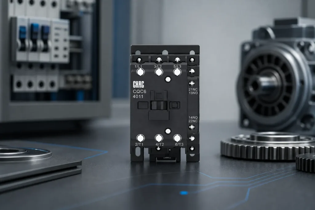
| Thermal or electronic overload relay | Detects overload and initiates the specified shutdown | Motor current, starting time, trip characteristics, and reset mode |
| Short-circuit protective device | Interrupts the specified fault current | Breaking rating at the operating voltage and documented coordination |
| Auxiliary contact block | Supports control logic or indication | Contact rating, function, and compatible mounting |
Schneider Electric’s Motor protection functions, last edited August 5, 2026, explains that overload relays must tolerate normal starting but respond to abnormally prolonged overload. It identifies nominal motor current and calculated starting time as selection inputs and describes IEC 60947-4-1 trip classes. This supports checking the starting profile, not choosing an overload solely because it mounts next to the contactor.
A control relay does not provide motor overload protection merely because its name includes “relay.” Conversely, a separate overload relay is not always necessary if another documented device already supplies the required motor-overload function. For the thermal overload relay route, verify the exact range and permitted starter combination rather than infer compatibility from the product family.
Short-circuit interruption is a separate check. Schneider Electric’s Fundamental characteristics of a circuit-breaker, last edited August 5, 2026, distinguishes operating voltage, overload settings, short-circuit settings, and breaking capacity. Do not treat the contactor’s load-current rating as a fault-interruption rating or assume every breaker also provides the required isolation function.
Does an overload reset mean the motor may restart?
No. Reset mode, coil commands, and the machine’s restart logic require separate review. The same motor-protection guide identifies automatic motor reclosing and locking out as control functions, not unavoidable consequences of choosing a contactor. Check what happens after an overload reset or loss and restoration of control power; do not presume that a persistent run command is either cleared or safely retained. The approved circuit and equipment instructions must determine when a new start command is required.
Which selection mistakes matter in motor and HVAC circuits?
| Mistake | Possible consequence | Review step |
|---|---|---|
| Using a general control-contact rating for motor power | Contact damage or unsuitable interruption duty | Check the documented motor-load rating |
| Omitting the required motor-overload function | Uncontrolled sustained overload and overheating | Identify the device and shutdown path providing that protection |
| Applying one utilization category to another load | Unsupported switching duty | Check the relevant load category at the actual voltage |
| Checking coil voltage but not control-supply capability | Chatter or failure to pull in | Verify documented coil demand and control-output capability |
| Copying a BOM without its operating conditions | Wrong pole, auxiliary, or protection configuration | Reconcile the nameplate, starting method, and circuit requirements |
| Assuming reset and restart are the same action | Unexpected return to operation | Review reset mode and restart permissions together |
Which CHAC contactors should an OEM evaluate?
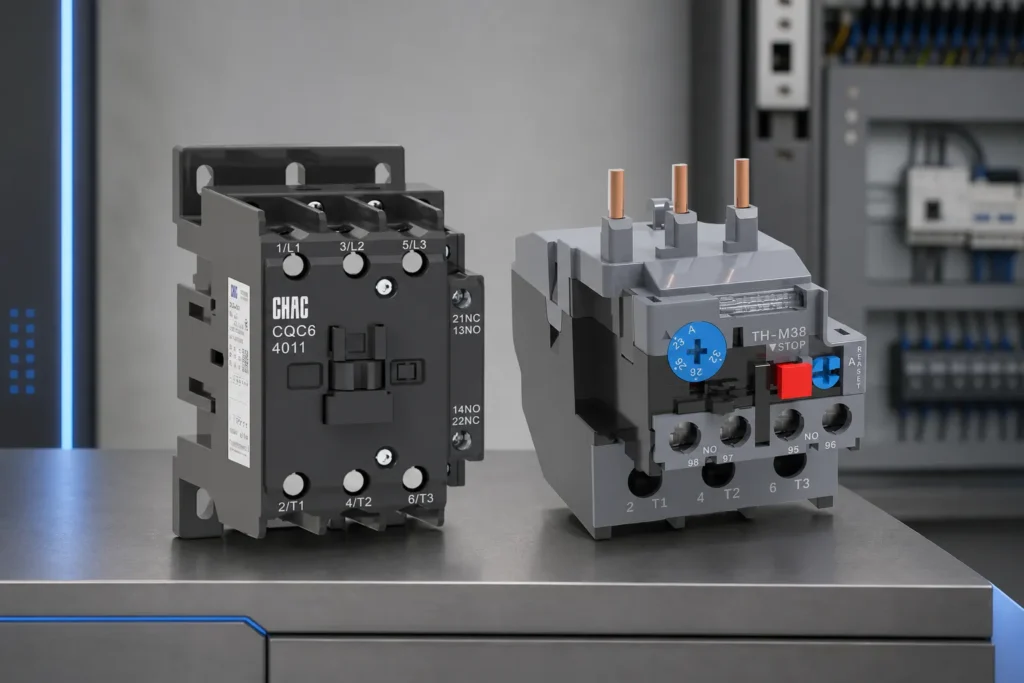
The AC contactor category and CQC6 Series Industrial AC Contactor page are starting points for product evaluation, not evidence that every configuration suits every motor. Obtain the exact model’s contact ratings, coil data, auxiliary options, and coordinated protection documentation before approving a substitution.
| Buyer should provide | Why it matters |
|---|---|
| Motor or load type and operational voltage | Defines the required power-contact duty |
| Full-load current, starting method, and starting time | Supports switching and overload selection |
| Operating frequency and service environment | Identifies conditions to check against published limits |
| Control supply and output characteristics | Determines the coil option and interface |
| Required auxiliary contacts and restart behavior | Defines control logic separately from power switching |
| Destination market and exact protective-device combination | Supports compliance and coordination review |
For EEA procurement, the European Commission’s CE marking guidance explains that the manufacturer declares conformity with applicable legal requirements; CE marking is not EU safety approval. Request the applicable declaration and model-specific supporting documentation. Do not infer US installation acceptance, a particular utilization category, or a coordinated starter rating from a CE mark alone.
What are the fit boundaries?
This comparison supports device-class selection for low-voltage motor and power switching. It does not replace:
- Motor cable sizing or voltage-drop calculations
- Short-circuit coordination studies
- Destination-market wiring and equipment requirements
- Specialized switching outside the selected product’s documented scope
Keep semiconductor soft-starter internals, VFD power stages, and protection-device coordination on their own specification paths. IEC duty descriptions and EEA conformity documentation do not establish compliance with a US installation’s applicable requirements. When project or model data is incomplete, obtain engineering review before locking the BOM.
What else do panel builders ask about contactors and relays?
What is the difference between a contactor and a relay?
A contactor commonly switches power loads; a control relay commonly switches logic, interlocks, and signals. Both must be selected by their documented contact duty. A general-purpose current rating does not prove that either device is suitable for a particular motor.
Can a relay replace a contactor on a three-phase motor?
Not simply because its amperage matches the motor’s running current. Use a contactor or starter rated for the motor duty, unless the alternative device has explicit ratings and documentation supporting that application. A relay can still switch the coil circuit or provide auxiliary logic.
What is a magnetic contactor used for?
A magnetic contactor uses an electromagnetic mechanism to operate its contacts. It commonly enables remote or automatic power switching in motor starters, pumps, HVAC equipment, and other documented load applications. Its operating mechanism does not itself provide motor overload protection.
Do contactors need overload protection separate from relays?
The motor circuit needs the applicable overload-protection function, but it does not always need a separate overload relay if another documented device supplies that function. A contactor primarily switches power; an ordinary control relay is not a motor-overload device. Check short-circuit protection separately as well.
How do lighting contactors differ from motor contactors?
The relevant load ratings and switching conditions differ. Select the device using its documented lighting or motor duty at the operating voltage, rather than transfer a motor-category rating to a lighting branch or vice versa.
What coil voltage should I specify for an AC contactor?
Specify the actual control supply and the manufacturer’s matching coil option, including AC or DC and frequency where applicable. Then check supply variation, pickup demand, and the output or transformer capability. The main-circuit AC rating does not determine the coil supply.
How do panel builders choose between contactor and relay for HVAC loads?
Check compressor or fan power-switching duty separately from thermostat logic, interlocks, and alarm signals. The power-path device needs the documented load rating; control relays may handle the auxiliary circuits within their own ratings. Do not size the entire arrangement from thermostat-contact data.
Will a motor automatically restart after an overload relay resets?
That depends on the reset mode and approved control circuit, not on the contactor alone. Review whether a run command persists after a trip or power interruption and what restart permission is required. Resetting protection must not be treated as proof that the fault is cleared or restart is authorized.
Which sources support the protection and compliance distinctions?
- Schneider Electric, Motor protection functions, last edited August 5, 2026: overload selection, starting time, and separate reclosing/lockout functions.
- Schneider Electric, Fundamental characteristics of a circuit-breaker, last edited August 5, 2026: operational voltage, trip settings, breaking capacity, and suitability for isolation.
- European Commission, CE marking, checked October 7, 2026: manufacturer conformity responsibilities and limits of the mark.
What should determine the final selection?
Choose by the work each device must perform, not by a single amperage label. Start with the load and switching duty, verify the power contacts, and then check the coil supply and its control interface. Establish overload and short-circuit protection independently, using documentation for the actual combination. Finally, review auxiliary signals, reset behavior, and restart permissions so the control sequence matches the equipment requirements. A suitable contactor can still belong to an unsuitable starter if these other functions are left undefined. For an OEM program, CHAC’s industrial control customization route can frame a model-specific documentation discussion after the electrical requirements are clear.