A single-gang faceplate can look right while the box behind it is wrong for the wall. A mounting bracket may hit a stud, a deep device may leave too little room for its conductors, or an oversized opening may leave an old-work box without proper support. Ordering by “one gang” alone therefore creates a fitting problem that cannot always be solved with a larger cover. This guide separates the dimensions that control installation, gives a traceable manufacturer example and explains what to verify before a wall is cut or a purchase order is approved.
The useful answer is that single gang electrical box dimensions are model-specific. For example, Allied Moulded lists its P-181 new-work box as 3-3/4 in high, 2-5/16 in wide and 2-5/8 in deep, with 18 cu. in. of volume. Those values describe that product, not every one-gang box and not an automatic cutout template. Select a box whose approved wiring method, mounting system, capacity and device clearance suit the project, then use its current drawing and instructions to determine the actual opening and finished-wall position.
Which dimensions matter before the wall is cut?
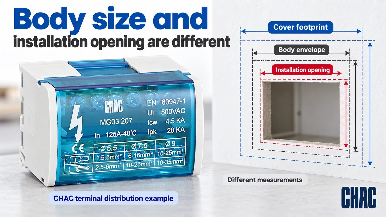
Separate the body envelope, wall opening, mounting projections and cover footprint. The body may pass through an opening while an external bracket cannot. An old-work clamp needs clearance to move and an appropriate wall surface to bear against. A new-work nail-on box uses a different mounting method and should not be specified as though it were a retrofit box.
The dimensions of a single gang electrical box also need a reference plane. Depth measured from the box front is not the same as the available space behind the finished surface. Wall board, tile, a mounting ring and the position of a stud all affect the final arrangement. Record the finished surface rather than measuring only the open framing.
| Measurement | What it controls | Common mistake |
|---|---|---|
| Body height and width | Physical fit within the wall | Using cover dimensions instead |
| Installation opening | Insertion and permitted support | Cutting directly from a generic size chart |
| Body depth | Space behind the finished surface | Ignoring masonry or service obstructions |
| Bracket and clamp envelope | Fastening clearance | Checking only the box shell |
| Marked volume | Box-fill evaluation | Assuming visible free space proves compliance |
What happens to the box position when tile is added later?
Use the final wall surface as the installation reference. For a hypothetical geometry example, assume a box front was flush with the original board and a later tile-and-adhesive finish adds 12 mm in front of that surface. Without another change, the box front is now 12 mm behind the new finish. The number describes the changed relationship; it is not a statement that this setback is permitted.
Check the adopted rules and the product’s permitted extension or mounting arrangement before fitting the device. A thicker decorative plate does not move the box, restore its support or create usable wiring volume. Specify the finish build-up while the wall is still being coordinated, including the final device mounting plane. If the finish changes after approval, review the box position and compatible parts again rather than asking the installer to compensate with longer screws alone.
What does an actual single-gang product record show?
The Allied Moulded P-181 product record, checked October 19, 2026, identifies a PVC box for nonmetallic-sheathed cable with angled mid nails and new-work installation. It lists ANSI/UL 514C for the product. This example is useful because the mounting method and intended wiring system appear beside the dimensions; selecting only the numbers would lose important information.
| P-181 published item | Value | How to use it |
|---|---|---|
| Height | 3-3/4 in | Check the specified body envelope |
| Width | 2-5/16 in | Check framing and adjacent services |
| Depth | 2-5/8 in | Compare with the finished-wall cavity |
| Volume | 18 cu. in. | Use for the applicable fill evaluation |
| Installation | New work, angled mid nails | Do not treat it as an old-work clamp box |
These are manufacturer data for one model, not a cross-brand compatibility claim. A different single-gang box can have another depth, capacity or mounting arrangement. In particular, do not copy this model’s dimensions into a drawing for a metal box, an imported back box or an enclosure intended for another wiring system.
How much depth does the device actually need?
Start with the device’s installed depth and terminal arrangement, then check the conductors and connectors behind it. A deep electronic dimmer, GFCI receptacle or smart control can make a nominally adequate cavity difficult to assemble. The device must reach its proper mounting position without crushing insulation or using the mounting screws to force the wiring into place.
Box fill and practical fit are separate checks. A box with enough calculated volume may still have poor access around a bulky connector or an entry fitting. Conversely, a device that can physically be pushed inside does not prove that the required volume is available. Apply the locally adopted rules to the actual conductors, grounding arrangement, clamps and device yokes instead of using a universal “number of wires per box.”
When does metal or plastic change the selection?
Material choice follows the permitted wiring method, mechanical exposure and installation approval. A metal box needs the appropriate bonding arrangement; a nonmetallic box still needs an approved cable-entry and fastening method. Neither material is automatically the correct choice for every indoor wall.
Fire-rated wall assemblies need another check. A box listing and an assembly’s permitted box spacing, opening and installation conditions are not interchangeable. The P-181 page includes model-specific fire-classification conditions. Those conditions should be checked in the referenced documentation rather than shortened to “all plastic boxes are fire rated.”
What should a first installation sample confirm before openings are repeated?
Assemble one representative box, device and matching plate in a de-energized sample of the intended wall construction. Check the actual mounting method, finished thickness, device seating and entry arrangement against their instructions. Use the chosen manufacturer’s opening template; do not derive it from the plate’s outside measurement. This check is particularly useful where many identical openings will be made.
Retain the model codes, drawing revisions and approved template with the sample record. A substitute device can have a deeper body or differently placed terminals even if the same plate fits its face. A substitute box can change clamp movement or mounting projections. Revisit the affected fit and capacity checks when either part changes. A successful sample establishes that particular reviewed configuration, not universal interchangeability between single-gang products.
What should be included in a supplier drawing review?
For a specified single gang electrical box size, request the exact part number, dimensioned drawing, capacity marking, wall-thickness limits, installation method and intended device or cover. Check cable-entry positions before deciding which side of a stud will carry the box. The fitting that enters the box may occupy space outside the shell as well as inside it.
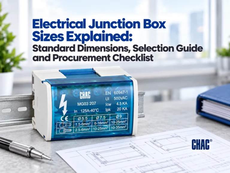
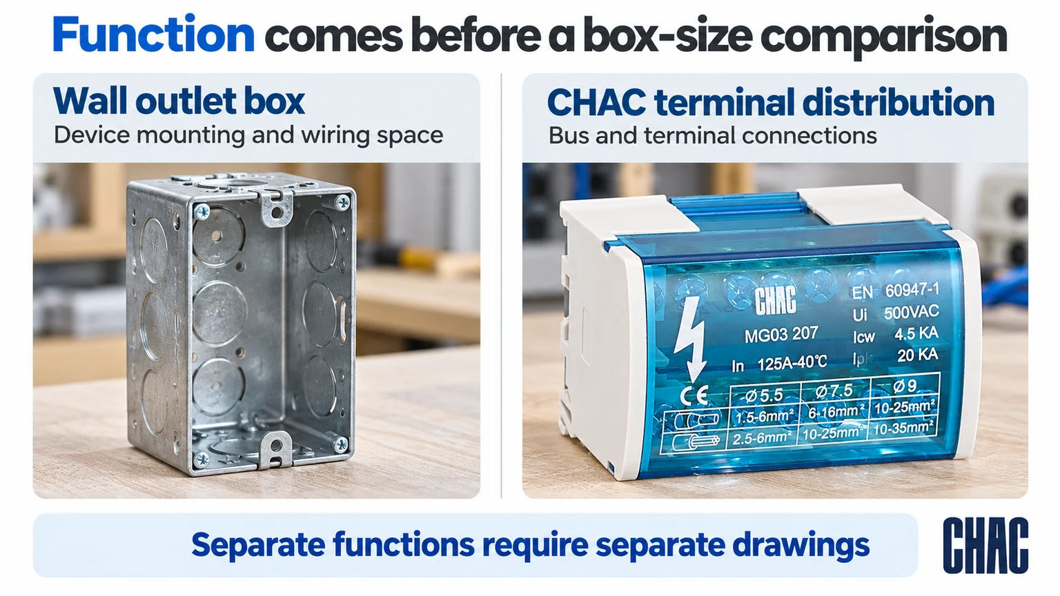
CHAC’s distribution junction box is a bus and terminal connection assembly, rather than the single-gang outlet box in this example. Its product drawing serves a different job. For wider projects, compare the electrical distribution components by function and keep the wall-box specification separate. A shared “junction box” description is not evidence of mechanical or regulatory interchangeability.
What questions come up about single-gang box dimensions?
What are the standard dimensions of a junction box?
There is no single set of dimensions for all junction boxes. Select the family and exact model, then verify its body envelope, capacity, entries, mounting and cover.
What is the 6 12 rule in electrical?
The expression commonly refers to dwelling receptacle-spacing requirements, rather than electrical-box dimensions. Its applicability and exceptions depend on the adopted installation code; it does not determine the wall cutout.
What are the code requirements for junction boxes?
Requirements depend on the installation and adopted code. Relevant checks include suitability, accessibility, fill, cable or raceway entries, mounting and grounding or bonding where required.
What are the dimensions of a single gang box cut out?
Use the selected box manufacturer’s installation template or drawing. Body dimensions, cover size and cutout dimensions are different, especially with retrofit clamps or mounting brackets.
What are the standard sizes for single gang junction box dimensions?
One gang describes a device arrangement, not one universal external size. The cited P-181 example is 3-3/4 by 2-5/16 by 2-5/8 inches, but other models differ.
How deep should single gang junction box dimensions be for the wiring inside?
Choose enough depth for the actual device, permitted conductor arrangement, connectors and required fill. Confirm that this depth fits the finished wall and allows the box to be mounted correctly.
References
- Allied Moulded P-181: model dimensions, volume and installation type; accessed October 19, 2026
- Hubbell RACO box families and intended applications; accessed October 19, 2026
- Hubbell RACO multi-gang boxes and covers; accessed October 19, 2026
Conclusion
A single-gang designation starts the selection; it does not finish the drawing. First establish the installation method and the device to be fitted, then compare the box envelope, capacity, entry positions and mounting clearance with the finished wall. Use the actual template for the opening and the applicable rules for fill, rather than assuming that a familiar faceplate guarantees compatibility. Product-specific approval and wall-assembly conditions still matter when the dimensions appear suitable. CHAC provides documented distribution and connection components for the parts of a project that match those functions. Keeping their specifications separate from the wall outlet box helps buyers request the correct drawing and avoid ordering different products under the same generic name.
For the relevant model drawings and project documentation, contact CHAC with the circuit requirements.