Ohm’s Law Calculator
Use the Ohm’s law formula to calculate DC current and resistive power from voltage and resistance. Includes I = V/R, P = V²/R and a 24 V worked example.
Calculate steady-state current and power for an ideal DC resistive load.
Result
DC current
2.00APreliminary calculationI = V / R; P = V² / RIdeal steady-state DC resistance. Temperature dependence, tolerances and AC reactance are excluded.
Why this result?
Formula and method
Use the Ohm’s law formula to calculate DC current and resistive power from voltage and resistance. Includes I = V/R, P = V²/R and a 24 V worked example.
How to use this calculator
- Enter the DC voltage across the resistor.
- Enter a positive resistance.
- Read current and dissipated power, then verify component ratings.
Calculation limits
Does not model nonlinear loads, inrush, AC impedance, temperature changes or component power derating.
Ohm’s law formula: current, resistance and power
Ohm’s law relates the voltage across a resistance to the current through it: V = I × R. For an ideal fixed DC resistance, current is V/R and dissipated power is V²/R. The calculated watts become heat that the component must safely dissipate.
Input notes
| Input | What to check |
|---|---|
| DC voltage | Use the voltage across the resistance itself. Supply voltage is appropriate only if other circuit voltage drops are negligible. |
| Resistance | Enter ohms, not kilohms. For example, 1 kΩ is 1,000 Ω. The value must be greater than zero. |
| Operating conditions | The model assumes constant resistance. Temperature, component tolerance and self-heating can change the actual value. |
Worked example · initial form values
12 Ω resistance across a 24 V DC supply
24 V DC across the resistance · 12 Ω
Current = 24 / 12 = 2.00 A
Power = 24² / 12 = 48.00 W
2.00 A
The resistance dissipates 48 W in the ideal model. A small signal resistor is unsuitable for that duty; check the component’s power rating, thermal derating and mounting requirements.
Where the simple model stops
- For a fixed resistance, doubling voltage doubles current and quadruples power. Check the maximum operating voltage and heat dissipation before applying a higher supply voltage.
- Do not infer a motor, LED driver or electronic power supply’s current from its DC resistance. Nonlinear loads, switching circuits and AC inductance or capacitance require a different model.
Frequently asked questions
Does this work for any AC or electronic load?
No. The model describes ideal steady-state DC resistance. AC reactance, nonlinear electronics, transient effects and temperature changes are excluded.
Can I also calculate resistance or voltage?
The relationships are R = V/I and V = I × R. This page’s form specifically takes voltage and resistance and returns current and resistive power.
Can I enter zero resistance for a short circuit?
No. The ideal formula would give unbounded current. Real fault current depends on source and circuit impedance, which this tool does not model.
Does Ohm’s law apply to an AC circuit?
For a purely resistive AC load, RMS quantities can be related through resistance. This calculator is labelled for steady DC and does not model complex impedance, phase shift or AC power factor.
Need help choosing a CHAC product?
Send the system voltage, load current, and installation conditions with your inquiry.
Application example · Illustrative inputs
Sizing the calculation for a resistive control-cabinet load
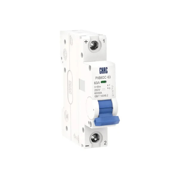
For a simple control-cabinet calculation, place an ideal 48 Ω resistive load across 24 V DC. The result is 0.50 A and 12 W of dissipated power. This helps establish a load-current reference before reviewing wiring and a DC protective device such as the CHAC PXB6DC-63 range. The resistor itself is not presented as a CHAC product, and 12 W of dissipation is not automatically an adequate component rating. Check temperature and duty against its own specifications. A contactor coil or electronic load may also behave differently from a fixed resistor, especially during starting.
Product data: PXB6DC-63 DC Miniature Circuit Breaker
Related CHAC products
Review DC protection and switching data after calculating the resistive load current.