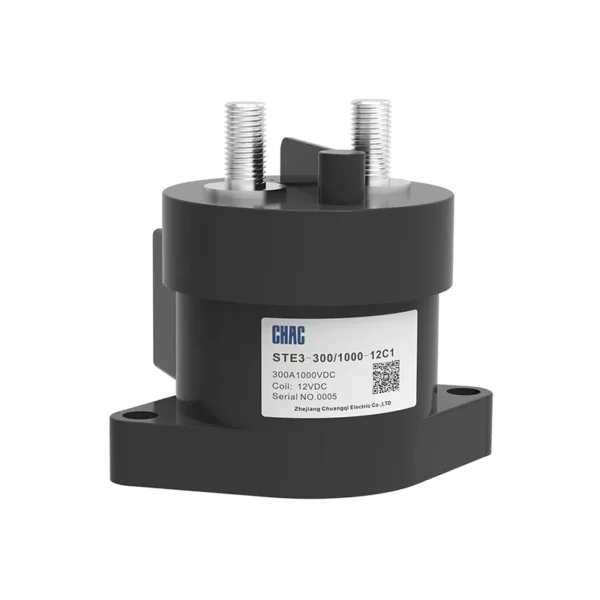
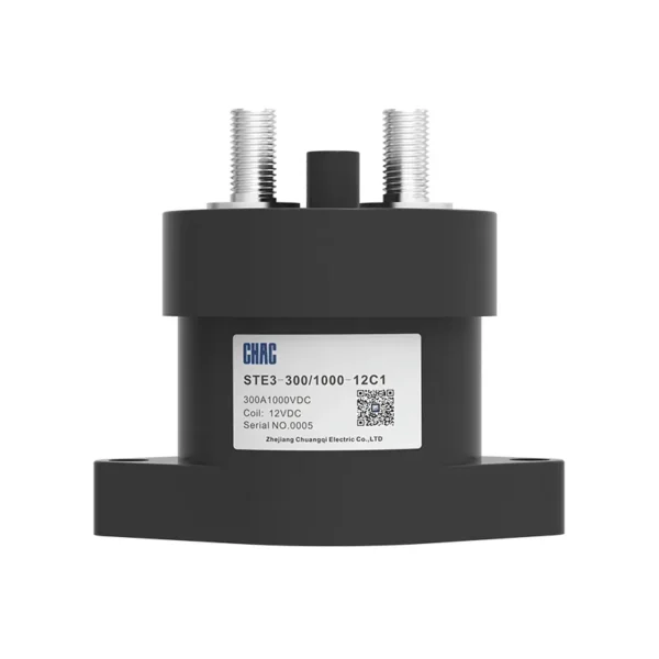
STE3 Series High-voltage DC contactor (Round Ceramic Sealing)
The STE3 Series High-voltage DC contactor (Round Ceramic Sealing) is a CHAC high-voltage DC contactor for controlled DC switching and isolation. The page keeps the model-specific technical table and original product images so buyers can verify voltage, current, configuration, mounting and applicable standards before ordering. Final suitability depends on the complete circuit, installation method and destination-market rules.
Product Overview
STE3 Series High-voltage DC contactor (Round Ceramic Sealing) is a high-voltage DC contactor intended for controlled DC switching and isolation. The current product record identifies it for battery, charging and high-voltage DC systems. Use the exact model variant and preserved technical source as the basis for procurement rather than assuming that every family member has the same rating.
Verified source summary: Technical Specifications Product model STE3-50 STE3-100 Contact form 1H 1H Auxiliary contact / / Contact polarity Having polarity Having polarity Contact resistance ≤3mΩ(at 50A) ≤3mΩ(at 100A) Operating voltage ≤75%Un ≤75%Un Maximum breaking current 50A 100A Electrical endurance 10~1000V 10~1000V Maximum breaking current 1000A(300VDC) 1000A(300VDC) Electrical endurance 600 times(1000V,50A) 500 times(1000V,50A) Current
Key Features
Typical Applications
Typical use can include battery, charging and high-voltage DC systems when the project confirms system voltage, current, fault or surge exposure, conductor and enclosure requirements, and the selected variant’s installation instructions. This page does not replace the project design or the authority having jurisdiction.
Applications and Selection Guide
Use the following decision points with the preserved model data. Product-family descriptions explain intent, but the exact technical table controls the ordered variant.
| Selection point | STE3 Series High-voltage DC contactor (Round Ceramic Sealing) | What the project must confirm |
|---|---|---|
| Application | High-Voltage DC Contactor projects | Confirm the actual system and environment |
| Selection basis | controlled DC switching and isolation | Use the exact model and technical table |
| Installation | Follow the model instructions | Check mounting, clearances and termination |
| Compliance | Use the listed standard where applicable | Verify edition, scope and destination rules |
| Adjacent product | Evaluate the related CHAC family where function differs | Do not substitute without engineering review |
Function
controlled DC switching and isolation
Match the protection or switching function to the system.
Configuration
Model-specific options
Confirm current, voltage, poles, terminals or accessories from the table.
Installation
Mechanical and electrical fit
Check enclosure, mounting, wiring space and maintenance access.
Project evidence
Documents and test records
Retain the approved drawing, technical sheet and commissioning record.
Ordering Guide
- State the exact model and variant.
- Provide the system voltage, current, frequency and load or protection function.
- Confirm mounting, terminals, accessories, enclosure and environmental conditions.
- Share quantity, destination market and required technical documents.
Installation and Coordination Checks
- Verify the model’s ratings and connection arrangement against the project drawings.
- Check conductor, busbar, enclosure, clearances and tightening requirements using the product documentation.
- Coordinate upstream and downstream protection or control devices where applicable.
- Use qualified personnel for installation, testing, isolation and maintenance.
Technical Specifications
| Product model | STE3-50 | STE3-100 | |
| Contact form | 1H | 1H | |
| Auxiliary contact | / | / | |
| Contact polarity | Having polarity | Having polarity | |
| Contact resistance | ≤3mΩ(at 50A) | ≤3mΩ(at 100A) | |
| Operating voltage | ≤75%Un | ≤75%Un | |
| Maximum breaking current | 50A | 100A | |
| Electrical endurance | 10~1000V | 10~1000V | |
| Maximum breaking current | 1000A(300VDC) | 1000A(300VDC) | |
| Electrical endurance | 600 times(1000V,50A) | 500 times(1000V,50A) | |
| Current carrying | 50A:Continuous for 200A:10min 300A:10s |
100A:Continuous for 200A:10min 300A:10s |
|
| Dielectric withstand voltage | Between open contacts | 2500VAC | 2500VAC |
| Between contact coils | 2500VAC | 2500VAC | |
| Mechanical Endurance | 2×10⁵ times | 2×10⁵ times | |
| Coil Voltage | 12V,24V | 12V,24V | |
| Coil power consumption | 5.5W | 5.5W | |
| Load extraction method | Internal thread | Internal thread and screw | |
| Coil lead out method | lead wire | lead wire | |
| Weight | About 180g | About 180g | |
| Vibrate | 10Hz~500Hz 49m/s² | 10Hz~500Hz 49m/s² | |
| Humidity | 5%~85%RH | 5%~85%RH | |
| Humidity range | -40℃~+85℃ | -40℃~+85℃ | |
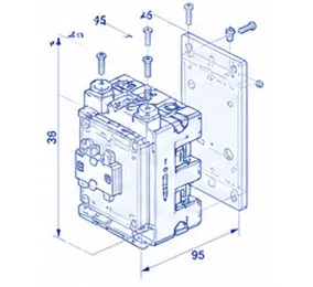
| External dimensions (mm) | 55.2×39.6×57.8 | 55.2×39.6×57.8 | |
| Product model | STE3-150 | STE3-200 | STE3-250 | |
| Contact form | 1H | 1H | 1H | |
| Auxiliary contact | NO | NO | NO | |
| Contact polarity | Having polarity | Having polarity | Having polarity | |
| Contact resistance | ≤1.5mΩ(at 150A) | ≤1.5mΩ(at 200A) | ≤1.5mΩ(at 250A) | |
| Operating voltage | ≤75%Un | ≤75%Un | ≤75%Un | |
| Maximum breaking current | 150A | 200A | 250A | |
| Electrical endurance | 10~1000V | 10~1000V | 10~1000V | |
| Maximum breaking current | 1600A(300VDC) | 2000A(300VDC) | 2000A(300VDC) | |
| Electrical endurance | 50 times(1000V,150A) | 30 times(1000V,200A) | 15 times(1000V,250A) | |
| Current carrying | 150A:Continuous for 400A:10min 800A:10s |
200A:Continuous for 400A:10min 800A:10s |
250A:Continuous for 400A:10min 800A:10s |
|
| Dielectric withstand voltage | Between open contacts | 4000VAC | 4000VAC | 4000VAC |
| Between contact coils | 4000VAC | 4000VAC | 4000VAC | |
| Mechanical Endurance | 2×10⁵ times | 2×10⁵ times | 2×10⁵ times | |
| Coil Voltage | 12V,24V | 12V,24V | 12V,24V | |
| Coil power consumption | Start 45W, maintain 2.8W | Start 45W, maintain 2.8W | Start 45W, maintain 2.8W | |
| Load extraction method | External thread | External thread | External thread | |
| Coil lead out method | lead wire | lead wire | lead wire | |
| Weight | 440g | 440g | 440g | |
| Vibrate | 10Hz~500Hz 49m/s² | 10Hz~500Hz 49m/s² | 10Hz~500Hz 49m/s² | |
| Humidity | 5%~85%RH | 5%~85%RH | 5%~85%RH | |
| Humidity range | -40℃~85℃ | -40℃~85℃ | -40℃~85℃ | |
| External dimensions (mm) | 80.3×66×64.3 | 80.3×66×64.3 | 80.3×66×64.3 | |
Note:
1.The above parameters are all initial values,measured at room temperature of 23℃.
2.Unless otherwise specified,the electrical durability tests are conducted on resistive loads with a on/off ratio of 0.6s:5.4s.
| Product model | STE3-300 | STE3-350 | |
| Contact form | 1H | 1H | |
| Auxiliary contact | NO | NO | |
| Contact polarity | Having polarity | Having polarity | |
| Contact resistance | ≤1.5mΩ(at 300A) | ≤1.5mΩ(at 350A) | |
| Operating voltage | ≤75%Un | ≤75%Un | |
| Maximum breaking current | 300A | 350A | |
| Electrical endurance | 10~1000V | 10~1000V | |
| Maximum breaking current | 2000A(300VDC) | 2000A(300VDC) | |
| Electrical endurance | 300A:Continuous for 400A:10min 600A:30s |
350A:Continuous for 400A:10min 800A:10s |
|
| Current carrying | 10 times(1000V,300A) | 50 times(1000V,300A) | |
| Dielectric withstand voltage | Between open contacts | 3300VAC | 3300VAC |
| Between contact coils | 3300VAC | 3300VAC | |
| Mechanical Endurance | 2×10⁵ times | 2×10⁵ times | |
| Coil Voltage | 12V,24V | 12V,24V | |
| Coil power consumption | Start 45W, maintain 2.8W | Start 45W, maintain 2.8W | |
| Load extraction method | External thread | External thread | |
| Coil lead out method | lead wire | lead wire | |
| Weight | 440g | 440g | |
| Vibrate | 10Hz~500Hz 49m/s² | 10Hz~500Hz 49m/s² | |
| Humidity | 5%~85%RH | 5%~85%RH | |
| Humidity range | -40℃~85℃ | -40℃~85℃ | |
| External dimensions (mm) | 80.3×66×64.3 | 80.3×66×64.3 | |
Note:
1.The above parameters are all initial values,measured at room temperature of 23℃.
2.Unless otherwise specified,the electrical durability tests are conducted on resistive loads witha on/off ratio of 0.6s:5.4s.
When the contactor is used in the charging circuit,a pre-charging circuit should be added to keep the impulse current below the rated make current.
As shown in the figure,first close the main negative contactor,then close the pre-charging contactor,and finally close the main positive contactor.If there is no pre-charging circuit,transient high current will be generated at the moment of the main contactor closing,which may cause the main positive contactor to stick.Please be careful.

The rated values in the contact parameters are all values for resistive loads.When using an inductive load (L load)with L/R>1ms,please install surge absorbing elements in parallel at both ends of the inductive load.Without taking measures,it may cause a decrease in electrical lifespan and result in poor continuity.
The on/off reliability of the product may change under small loads due to environmental conditions and on/off frequency,so it needs to be confirmed under actual loads.
This contactor is a DC high-voltage opening and closing device.In the final fault state,there may be a situation where it cannot be turned on or off.
Therefore,please do not use it beyond the capacity and frequency range specified in this manual.If it has reached the point where it cannot be connected or disconnected,it may lead to burning.A circuit structure that can cut off the current load in emergency situations should be adopted.To ensure safety,components should be replaced regularly.
For products that do not use coil drive boards or energy-saving versions,it is recommended to install nonlinear resistors (variable resistors are recommended)to suppress the reverse electromotive force of contactor coils.If diodes are used,the release time of the contactor will be greatly prolonged,which may lead to a decrease in cutting performance.Please be careful.
When conducting action voltage tests on products that use coil drive boards and energy-saving versions,the voltage should not slowly rise.Please use a fast rising edge(step power supply method)to drive the coil of the product,otherwise the contactor will not operate.At the same time,this type of product will automatically switch coil current after about 0.3 seconds of connection,and repeated on/off operations within 0.3 seconds will cause contactor failure.Please be aware.
It is strictly prohibited to place the contactor in an environment that exceeds the product temperature range(-40℃~+85℃) for a long time.
Please avoid installing near strong magnetic fields (transformers,magnets)and heating objects.
Ensure that the main power cord is closest to the outlet of the contactor.Then install and tighten in the order of flat washers,spring washers,and nuts.Incorrect connection sequence may cause severe overheating and lead to melting of the insulation layer of the connecting cable.
Please control the tightening torque of screws in each part within the specified range below.Beyond the range,it may cause damage to the ceramic sealing chamber and thread damage.In addition,the installation direction is not restricted.
| Load outlet end | Product shell installation part |
| M4 screws:2Nm ~ 3Nm | M4 screws:2Nm ~ 3Nm |
| M5 screws:3Nm ~ 4Nm | M5 screws:3Nm ~ 4Nm |
| M6 screws:6Nm ~ 8Nm | M6 screws:6Nm ~ 8Nm |
| M8 screws:8Nm ~ 10Nm |
Please avoid sticking foreign objects such as grease on the lead-out end;Please use the following specifications of connecting wires,otherwise it may cause abnormal heating of the lead-out section
| Current/A | Nominal cross-sectional area of conductor/mm² |
| 10 | ≥1.5 |
| 20 | ≥4 |
| 30 | ≥6 |
| 40 | ≥10 |
| 50 | ≥16 |
| 60 | ≥16 |
| 100 | ≥35 |
| 150 | ≥70 |
| 200 | ≥95 |
| 250 | ≥150 |
| 300 | ≥185 |
| 350 | ≥240 |
| 400 | ≥300 |
| 500 | ≥370 |
| 600 | ≥480 |
| 800 | ≥600 |
The suction voltage and release voltage will change with the ambient temperature and usage conditions,so please pay attention!
If the coil and contacts are continuously energized using the rated voltage (current)and then cut off,and immediately re-energized,this contactor will experience an increase in coil resistance due to the temperature rise of the coil,resulting in an increase in the suction voltage and exceeding the rated suction voltage.At this time,please take the following measures to reduce the load current,limit the power on time,and apply a coil voltage that exceeds the rated voltage of the coil (quick start).
When opening and closing without load,the contact resistance may increase,so please be careful!
This product contains resin,so please do not use it in places or environments where gasoline,diluents,alcohol lamps,organic solvents,and strong alkaline substances such as ammonia and sodium hydroxide may be attached.
Please be careful not to attach grease or foreign objects to the board terminals,otherwise it may cause abnormal heating of the load terminals.
Why Choose CHAC
With 30+ years of manufacturing experience, 1100+ employees, 100M+ poles
annual capacity and 90% automated production, CHAC provides stable production capacity and strict
quality control for global OEM/ODM customers. Our in-house manufacturing system supports long-term
cooperation for electrical brands, importers and distributors.

30+
YEARS EXPERIENCE
Specialized in low-voltage electrical manufacturing

1100+
EMPLOYEES
Professional team ensures stable quality and delivery

100M+
POLES ANNUAL CAPACITY
Large-scale production capacity to meet global demand

90%
AUTOMATED PRODUCTION
Advanced automation for high efficiency and consistency
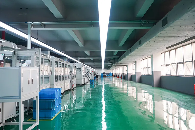
Automated Assembly Line

Testing Laboratory
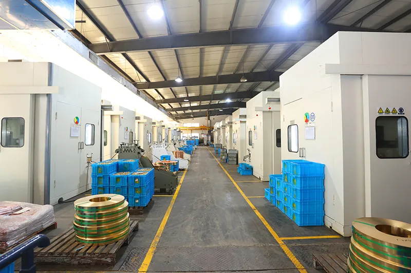
Injection & Stamping
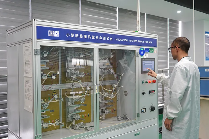
Quality Inspection



Strict quality control system ensures every product meets global standards.
What Can We Customize?
CHAC supports customization of coil voltage, auxiliary contact configuration,
electrical parameters, product branding,packaging design and engineering development according to customers’ equipment and market requirements.

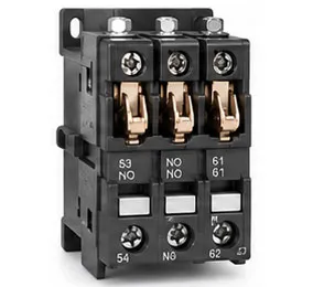
Coil Voltage
AC and DC coil voltage options tailored to application requirements.
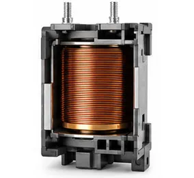

Auxiliary Contacts
Flexible auxiliary contact combinations for different control functions.

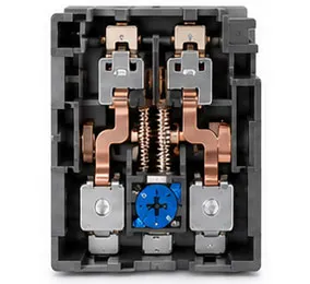
Electrical Parameters
Current ratings, protection ranges and functional parameters can be customized.

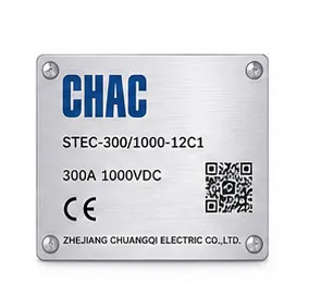
Product Branding
Private label logos, nameplates and product identification support.

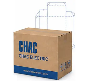
Packaging Design
Custom cartons, labels, manuals and packaging solutions.

Engineering Development
Support from drawing optimization to product development and application matching.
Download
STE Series High Voltage DC Contactor
Complete product overview for low-voltage electrical components and product selection reference.
Need Technical Documents?
Contact us for datasheets, certificates, drawings, selection guidance or OEM/ODM project support.
STE3 Product FAQ
What is the STE3 used for?
It is a high-voltage DC switching device for the system and variant shown in the technical table. Confirm the working voltage, current, polarity and load category.
Why does DC contactor polarity matter?
Some variants specify load or coil polarity because DC arc management and magnetic blowout depend on the internal design. Follow the marked polarity.
How do I select the voltage and current?
Use the actual steady, inrush and breaking current, system voltage, duty cycle and fault-clearing strategy. The family range is not a blanket rating for every variant.
What does ceramic or epoxy sealing change?
The sealing construction is part of the product design and environmental suitability. Compare the exact datasheet for temperature, insulation and endurance.
Can it switch a battery or charger circuit?
It may be suitable when the variant's DC voltage, current, breaking duty and insulation data match the application. Confirm the complete design.
What should be tested before energizing?
Check coil operation, contact resistance, insulation, polarity, pre-charge or discharge sequence and the emergency isolation procedure.
Confirm the Right STE3 Configuration
Send the exact model, operating conditions, quantity, destination market and required documents. CHAC will review the request against the published product data.