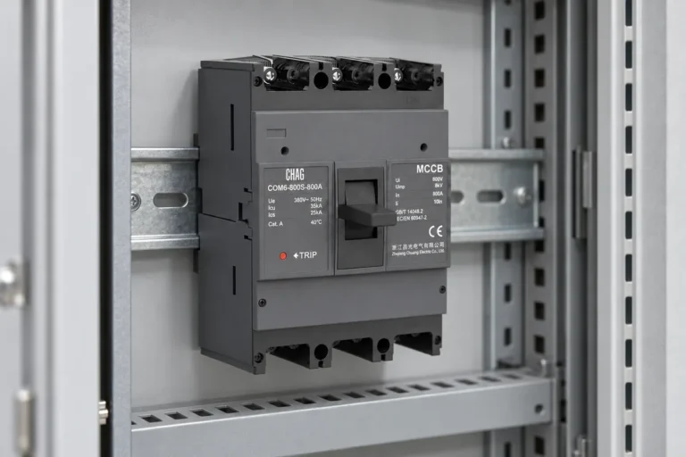
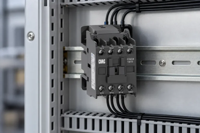
Panel builders size a thermal overload relay from motor full-load current, service factor, phase count, ambient temperature, and starter duty — then match a heater or electronic trip band and confirm coordination with the contactor and upstream short-circuit device.
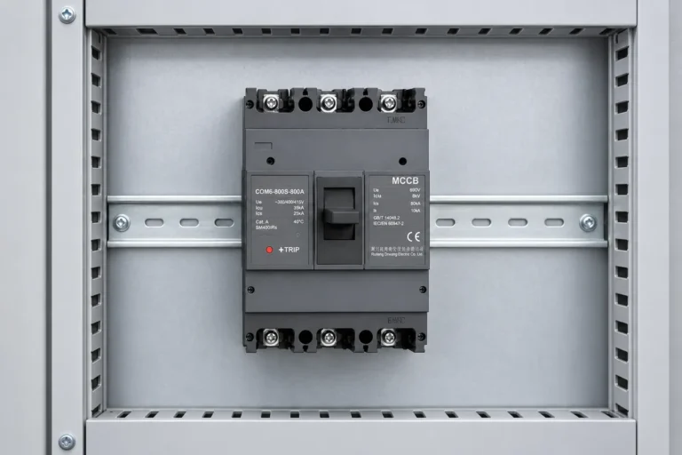
This guide focuses on three-phase motor branches in low-voltage starters. For contactor versus control-relay choices in the same assembly, see the AC contactor vs relay guide. For feeder-level molded case platforms, see the MCCB buying guide for OEM buyers.
Part 1. What does a thermal overload relay protect in a motor starter?
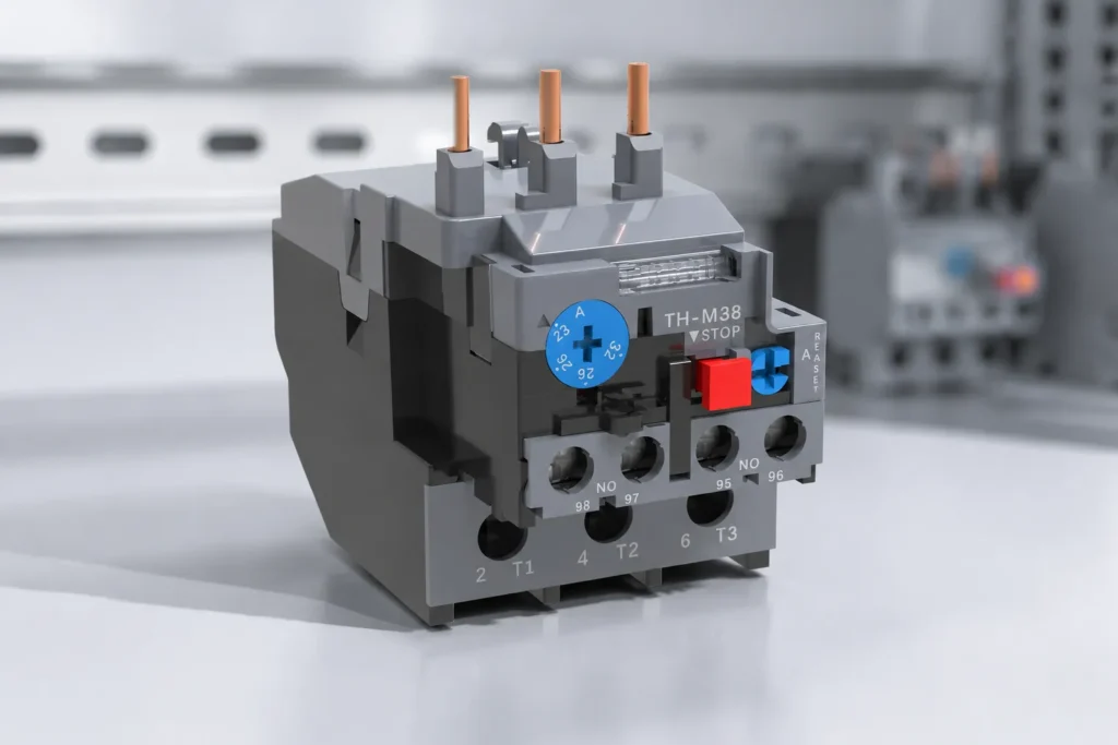
A thermal overload relay responds to sustained overcurrent that can overheat the motor winding — conditions that the upstream short-circuit device is not meant to tolerate for long periods. In a direct-on-line starter, the contactor switches power while the overload relay opens the control circuit (or trips the starter) when heat accumulation exceeds the selected trip characteristic.
Device in starter
Primary duty
Typical failure mode if wrong device
Short-circuit breaker / fuses
Fault-level interrupt
N/A for overload sustained minutes
Contactor
Frequent power switching
Welded contacts if undersized
Thermal overload relay
Sustained overcurrent / phase loss patterns
Motor burn if heater range too high
Control relay (optional)
Logic and interlocks
Mis-start, not thermal damage
IEC 60947-4-1 frames motor-starter assemblies as coordinated combinations of contactors and overload or other protective devices. Treat the overload as part of a starter kit, not a stand-alone catalog item.
Part 2. Which motor data points drive overload relay selection?
Heater tables and electronic trip curves start with nameplate data. Incomplete motor sheets are the main cause of nuisance tripping or inadequate protection.
Data point
Where it comes from
Selection impact
Full-load current (FLA)
Motor nameplate
Base for heater / trip band
Service factor
Nameplate
May adjust allowable continuous current
Voltage and phase (3P)
Nameplate and supply
Confirms three-pole overload assignment
Duty / starting method
Application (DOL, reversing, etc.)
Trip class and coordination
Ambient temperature
Installation environment
Derating per manufacturer data
Altitude (if applicable)
Site data
May reduce thermal capability
Three-phase checklist before ordering
Confirm each phase carries the overload sensing elements required by the starter design.
Record FLA at rated voltage, not horsepower alone.
Note starting frequency — frequent starts may need electronic trip with wider adjustment.
Capture reset type required (manual vs automatic) for maintenance policy.
List contactor frame already chosen so overload mounts and bus match.
Part 3. When is bimetallic overload enough versus electronic thermal protection?
Bimetallic thermal overload relays use heated bimetal strips to open contacts after sustained overload. Electronic thermal overload devices use sensors and adjustable trip parameters, often with closer matching to complex duty cycles.
Technology
Best fit when
Limitation
Bimetallic thermal
Standard DOL pumps, fans, compressors with stable duty
Integrated branch with short-circuit + overload function
Different coordination path (see Part 5)
If the application includes reversible plugging, inching, or heavy inching duty, review trip class and manufacturer guidance — do not assume the lowest heater step still protects the motor.
Part 4. How should overload relays pair with contactors in three-phase starters?
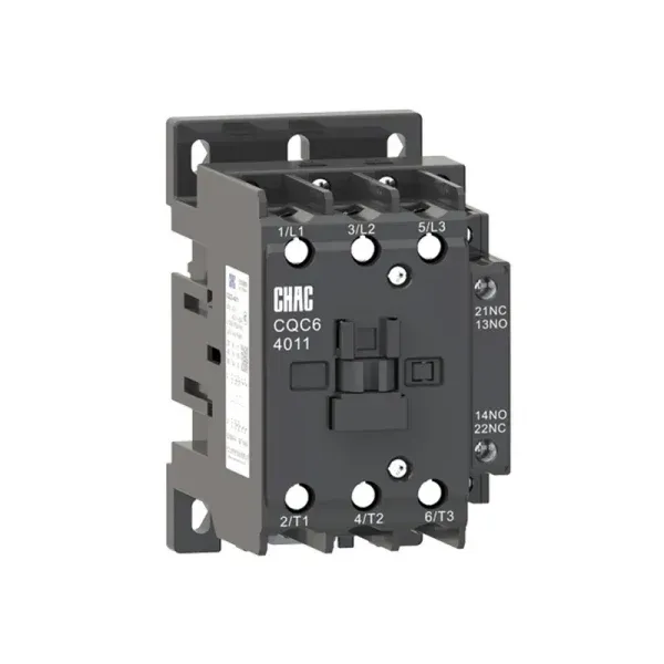
The overload relay mounts on or adjacent to the AC contactor and shares the motor power circuit. Control wiring typically routes overload auxiliary contacts to drop out the contactor coil on trip.
Breaker or fuses clear faults before overload heats
Document reset access
Manual reset location reachable for maintenance
Starter layouts for three-phase motors are documented in wiring diagrams such as the CQR2 thermal overload reference on CHAC media. Use the diagram as a layout pattern — final approval still requires project-specific motor data.
For contactor sizing and control-relay logic around the same assembly, cross-read the AC contactor vs relay guide.
Part 5. How do thermal overload relays differ from MPCBs in the same panel?
Both address motor branch protection, but the device class and coordination differ.
Aspect
Thermal overload relay in starter
Motor protection circuit breaker (MPCB)
Mounting
On contactor starter rail
Often standalone branch device
Short-circuit duty
Relies on upstream breaker/fuse
Integrates short-circuit trip function
Adjustment
Heater or electronic trip on overload
Combined motor-protector curves
Typical use
Classic DOL / reversing starters
Compact motor feeder modules
Do not specify both devices on the same motor branch without an engineered coordination study. Choose starter-based overload or MPCB feeder based on panel standard and local practice.
Part 6. Which CHAC routes support motor overload and starter programs?
Product recommendation
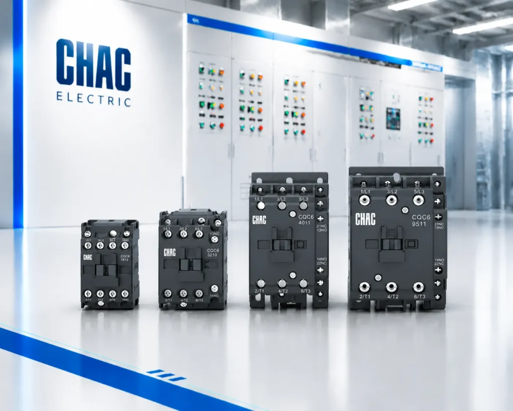
CHAC industrial control products include contactor platforms, thermal overload devices, and motor protection circuit breakers for OEM panel programs.
Submit motor nameplate data and starter single-line layout through Contact CHAC Electric for platform scoping.
Part 7. What are the fit boundaries for overload relay selection?
This guide supports low-voltage thermal overload relay selection for motor starters. It does not replace:
Motor cable sizing or voltage-drop calculations
Short-circuit coordination studies
VFD output protection or harmonic heating analysis
Medium-voltage motor protection
Explosion-proof or marine classification rules
When motor data is incomplete or duty is non-standard, hold heater approval until nameplate FLA and ambient conditions are confirmed.
FAQs
What is a thermal overload relay?
A thermal overload relay is a protective device in a motor starter that detects sustained overcurrent — usually through bimetallic heating or electronic sensing — and opens the control circuit or trips the starter to reduce motor overheating risk. It is coordinated with a contactor under motor-starter standards such as IEC 60947-4-1.
How do you size a thermal overload relay for a three-phase motor?
Start from motor full-load current on the nameplate, adjust for service factor and manufacturer ambient derating rules, select the heater or electronic trip band that covers that current, and verify the three-pole device matches the contactor frame and starter wiring layout.
What is the difference between a thermal overload relay and an MPCB?
A thermal overload relay protects against sustained overload in a contactor-based starter and relies on upstream devices for short-circuit interruption. An MPCB combines motor overload and short-circuit protection in one branch device. They serve different starter architectures and should not be duplicated on the same branch without engineering review.
What motor nameplate data is required for overload selection?
At minimum: rated voltage, full-load current, phase, service factor if listed, and intended duty. Starting method, ambient temperature, and altitude also affect trip selection when published derating applies.
Can one overload relay protect multiple motors?
Standard practice is one overload relay (or MPCB) per motor branch. Sharing one overload across multiple motors requires engineered interlocks and is uncommon in general industrial panels.
How does a thermal overload relay coordinate with a contactor?
The overload sits in the motor power circuit with the contactor and uses auxiliary contacts to de-energize the contactor coil when trip conditions occur. The contactor handles switching duty; the overload handles sustained overcurrent detection.
When should buyers choose electronic instead of bimetallic overload?
Choose electronic thermal protection when adjustable trip parameters, tighter duty matching, or diagnostic features justify the cost — especially with variable duty cycles, frequent starts, or wide ambient swings beyond standard bimetallic bands.