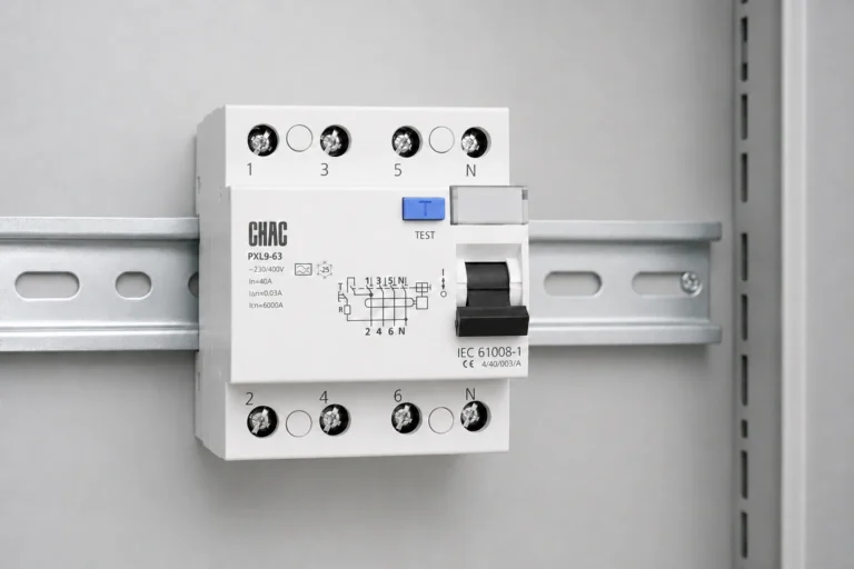
An RCCB that trips when another circuit is switched on is not automatically defective. A borrowed neutral can send return current outside the device’s sensing path, while an incorrectly selected residual-current type can leave a different problem: the device may not be suitable for the fault waveform produced by the load. For electrical contractors and distributors, these are separate checks, not interchangeable explanations. Copying a generic wiring diagram or choosing a larger ampere rating will not resolve both. This guide explains how to review conductor paths, distinguish current ratings from protection functions, assess electronic loads, and specify the documentation needed before a board is accepted. Installation and fault investigation belong to a qualified electrical professional following the equipment instructions and applicable local rules.
The short answer is that RCCB installation and wiring must keep all relevant live conductors of the protected circuit within the same sensing path, with protective earth outside it. An RCCB provides residual-current protection without integrated overload or short-circuit protection; an RCBO combines these functions. IEC 61008 and IEC 61009 address these different device families. A 30 mA residual-current rating and a current-carrying rating in amperes describe different characteristics, neither of which alone establishes suitability. Before choosing a device, verify the circuit arrangement, load waveform, overcurrent protection, manufacturer wiring diagram, and installation requirements.
What does an RCCB protect against?
An RCCB compares the sum of the currents passing through its residual-current sensing system. In a single-phase circuit, normal load current flows out through line and returns through neutral. Current returning by another route creates an imbalance. The RCCB operates according to its specified residual-current and time characteristics; it does not identify the cause of that imbalance.
An RCCB is not a substitute for overload or short-circuit protection. An MCB or suitable fuse performs the overcurrent duty in an RCCB arrangement, whereas an RCBO incorporates overcurrent and residual-current functions. Schneider Electric’s Electrical Installation Guide: Form factors of RCDs, updated 5 August 2026, distinguishes the device families and their applicable standards.
| Device arrangement | Residual-current function | Overcurrent function | Decision for the board designer |
|---|---|---|---|
| MCB alone | Not provided by the MCB itself | Overload and short-circuit protection | Determine whether separate residual-current protection is required. |
| RCCB with coordinated MCBs or fuses | Provided by the RCCB | Provided separately | Check both the RCCB’s protection requirements and the downstream circuit protection. |
| RCBO | Integrated | Integrated | Verify both sets of ratings and the particular circuit arrangement. |
A residual-current device does not make every contact with electricity safe. For example, current passing from line to neutral through a person can remain balanced through the sensing path. Earthing, bonding, insulation, isolation, and other required protective measures still need independent verification.
How should line, neutral, and protective earth be routed?
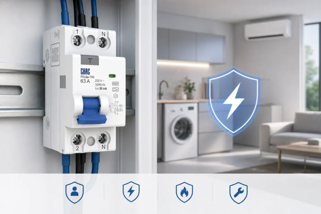
The essential wiring rule is a complete monitored current path, not a universal top-in/bottom-out terminal arrangement. The exact device diagram determines supply direction, neutral terminal position, permitted conductors, and any test-circuit connection requirements. Do not infer these details from a different model with a similar housing.
How is a single-phase RCCB connected?
Where the circuit has line and neutral, both pass through the designated RCCB poles and continue to the protected load. The protected neutral returns through that same device. Protective earth follows the installation’s earthing arrangement outside the residual-current sensing path; it is not used as a substitute load-return conductor.
What changes for a three-phase circuit?
All phases supplying the protected circuit must be included in the same sensing arrangement. Where the load uses a neutral, that neutral must also be included. A three-phase load without neutral requires a device and connection arrangement specifically permitted for that use; do not assume every four-pole product can be used without a neutral connection, because its test circuit may have additional requirements.
| Circuit arrangement | Current paths to account for | Manufacturer detail to confirm |
|---|---|---|
| Single-phase with neutral | Line and its returning neutral | Designated neutral terminal and supply/load markings |
| Three-phase with neutral | All three phases and their associated neutral | Four-conductor arrangement and neutral pole requirements |
| Three-phase without neutral | All three phases | Permitted connection and test-circuit operation without a load neutral |
Why does a shared or borrowed neutral cause tripping?
A borrowed neutral is a load-return path that belongs to a different protected circuit or lies outside the relevant RCCB. If line current passes through RCCB A but part of its return current passes through RCCB B, neither device sees the intended balance. Similarly, connecting a protected load to an unprotected neutral bar bypasses the monitored return path. This can cause tripping even when the load itself has no insulation fault.
A common neutral bar serving circuits downstream of one RCCB is not the same issue as connecting the downstream neutral bars of separate RCCBs together. The review must establish which protection group each line and neutral belongs to. Protective earth is a separate path again: a downstream neutral-to-earth connection can divert return current outside the sensing system. These explanations follow the current-balance principle; they do not replace a circuit-specific wiring assessment. Never disconnect protective earth or add a neutral-to-earth link to suppress trips.
How should RCCB current and sensitivity ratings be selected?
Does the ampere rating set the overload trip current?
No. The RCCB’s rated current, In, describes its current-carrying rating under the specified conditions, not an overload trip setting. Increasing In does not add overload protection. The separate overcurrent protective arrangement must protect the conductors and the RCCB against overload as required by its instructions and the installation design.
Short-circuit coordination is another check. The prospective fault current at the board and the RCCB manufacturer’s stated coordination with a specified short-circuit protective device, or SCPD, must be reviewed together. A conditional short-circuit rating is not evidence that an RCCB can independently interrupt that fault current. Do not substitute an arbitrary upstream MCB or fuse for the device specified in the coordination documentation.
Is 30 mA suitable for every installation?
No single residual-current setting applies to every circuit. The rated residual operating current, IΔn, is expressed in milliamperes and is distinct from In. A 30 mA device is commonly associated with additional protection, but its use and location depend on the applicable installation rules. Higher settings are not equivalent substitutes where additional protection is required; lower settings are not automatically a better choice for every load.
Consider the protective purpose, earthing arrangement, normal leakage from the connected equipment, and coordination with other residual-current devices. Do not increase IΔn merely to stop unexplained trips. The required sensitivity, timing, and selectivity need an installation-specific decision rather than a fixed application table.
What is the difference between Type AC, A, F, and B?
The type designation describes the residual-current waveforms a device is designed to detect. This is separate from its ampere rating, sensitivity, and upstream SCPD coordination. Schneider Electric’s Types of RCDs, updated 5 August 2026, explains the waveform distinctions with reference to IEC 60755 and IEC 62423.
| RCD type | Detection distinction | Selection boundary |
|---|---|---|
| Type AC | Sinusoidal AC residual current | Do not assume it covers rectifier or inverter fault waveforms, or that local rules permit it for the intended circuit. |
| Type A | Sinusoidal AC and pulsating DC residual current | Pulsating DC capability is not the same as smooth DC detection. |
| Type F | Type A characteristics plus specified composite-frequency residual currents associated with single-phase variable-speed drives | Do not treat it as a universal solution for every inverter or three-phase drive. |
| Type B | Sinusoidal AC, pulsating DC, specified composite-frequency currents, and smooth DC residual current | Relevant where the fault waveform requires it; the application name alone does not establish the requirement. |
How does DC detection affect EV charger selection?
Check the complete arrangement, including any residual direct-current detecting device (RDC-DD), rather than the external RCD type alone. Wallbox’s explanation of Sweden’s May 2024 SEK Handbook 444 requirements provides a scoped manufacturer example: it describes Type B or Type A with an IEC 62955 RDC-DD for certain models, and an integrated Type A plus RDC-DD arrangement for another. That example shows why built-in functions and external requirements must be checked model by model. It is not a worldwide installation rule or evidence that a CHAC device includes DC detection.
Does every solar inverter need a Type B RCCB?
No blanket recommendation follows from the label “solar PV.” Inverter architecture affects the possible residual-current waveform. The equipment instructions and applicable installation rules must establish whether an external RCD is required and which type is acceptable. If smooth DC residual current must be detected by the external RCD, Type A’s pulsating DC capability is not equivalent to Type B’s smooth DC capability.
An inverter’s reference to internal monitoring is not, by itself, proof that a particular external RCCB can be omitted or changed. Obtain the model-specific installation requirement and verify the complete protection arrangement. The waveform source above identifies PV among applications where rectifier characteristics can make Type B relevant; it does not prove that all PV installations require the same device.

Why does an RCCB keep tripping after installation?
A trip is evidence of an imbalance or an operating issue to investigate, not proof of a failed RCCB. A qualified person should distinguish the observed pattern, the circuit wiring, the load condition, and the device specification. The following table defines investigation priorities rather than live-testing instructions.
| Observed pattern | Possible explanation | What needs to be established |
|---|---|---|
| Trips when a different circuit operates | Borrowed neutral or interconnected protection-group neutral bars | Whether each load’s line and neutral pass through the same RCCB |
| Trips when one load is connected | Equipment leakage, insulation fault, or an unsuitable residual-current type | Equipment condition and documented waveform requirements |
| Trips as more loads operate | Accumulated leakage across the protected group | The installed loads’ leakage and whether circuit grouping meets the design requirements |
| Cannot reset or hold closed | Persistent downstream fault, connection problem, or device problem | The installation and device condition before returning the circuit to service |
| Test button does not produce the specified response | Incorrect supply/test-circuit connection or a device fault | The manufacturer’s test requirements and a qualified assessment |
Do not repeatedly reset a device without investigating a recurring fault, bypass its protective function, or remove earth connections. A replacement with a higher ampere rating does not correct a borrowed neutral; a change of waveform type does not repair damaged insulation. The RCD wiring and electrical safety guide provides related context, but the exact circuit and equipment documentation govern the decision.
What must be verified before an RCCB installation is accepted?
The test button checks the device’s built-in test function under its stated operating conditions. A successful test is useful, but it does not establish protective-conductor continuity, correct bonding, insulation condition, correct neutral grouping, or satisfactory protection throughout the installation. Handle reset is not an acceptance test either.
- Confirm the approved circuit diagram, supply arrangement, earthing system, and applicable installation requirements.
- Match voltage, frequency, current-carrying rating, residual-current sensitivity, timing, and waveform type to the design and equipment instructions.
- Verify terminal markings, permitted supply direction, conductor suitability, manufacturer tightening requirements, and the separation of protected neutrals.
- Document overload protection and short-circuit coordination, including the specified SCPD and the relevant fault-level assessment.
- Complete and record the required inspection and commissioning tests using the applicable procedure, in addition to the manufacturer’s test-button check.
This is a specification and acceptance checklist, not a procedure for working on energized equipment. Test methods, limits, and repeat-test intervals must come from the manufacturer’s instructions and the rules adopted for the project; a generic blog cannot establish them for every market.
Which compliance documents should an RCCB buyer request?
Keep product standards, legal conformity, certification scope, and installation acceptance separate. IEC 61008 concerns the RCCB device family without integral overcurrent protection; IEC 61009 concerns RCBOs with integral overcurrent protection. A reference to either standard is not itself proof that a particular model has been independently certified.
The European Commission’s CE marking guidance explains that the manufacturer declares conformity with applicable legal requirements and must carry out conformity assessment, prepare the technical file, and issue the EU declaration of conformity. CE marking does not mean that the EU or another authority has approved a product as safe. For an EEA purchase, check the declaration against the exact supplied model and applicable legislation rather than accepting a logo alone.
For US panelboard applications, IEC or CE documentation does not establish interchangeability with listed equipment. The UL Solutions Panelboard Application Guide distinguishes certification and classification scopes and explains the importance of product markings and installation instructions. Verify the equipment’s permitted use, certification scope, and the locally adopted requirements with the responsible designer or authority. No UL status is inferred for the products linked here.
How should distributors compare RCCB offers?
Compare offers against the same protection requirement, not just price per pole. A shared RCCB arrangement can affect several downstream circuits when it trips, while circuit-level protection changes the board layout and fault-isolation arrangement. Neither design is universally preferable; assess the required continuity of service, available space, installation rules, and documented protection coordination before comparing purchasing costs.
Request a model-specific package containing the wiring diagram, ratings, waveform designation, terminal and mounting requirements, coordination documentation, and applicable conformity or certification evidence. Missing documents can delay board approval or require redesign even when a product fits physically. CHAC’s RCCB breaker category is a starting point for identifying products; the category name does not confirm an individual model’s suitability for EV, PV, or another electronic load.
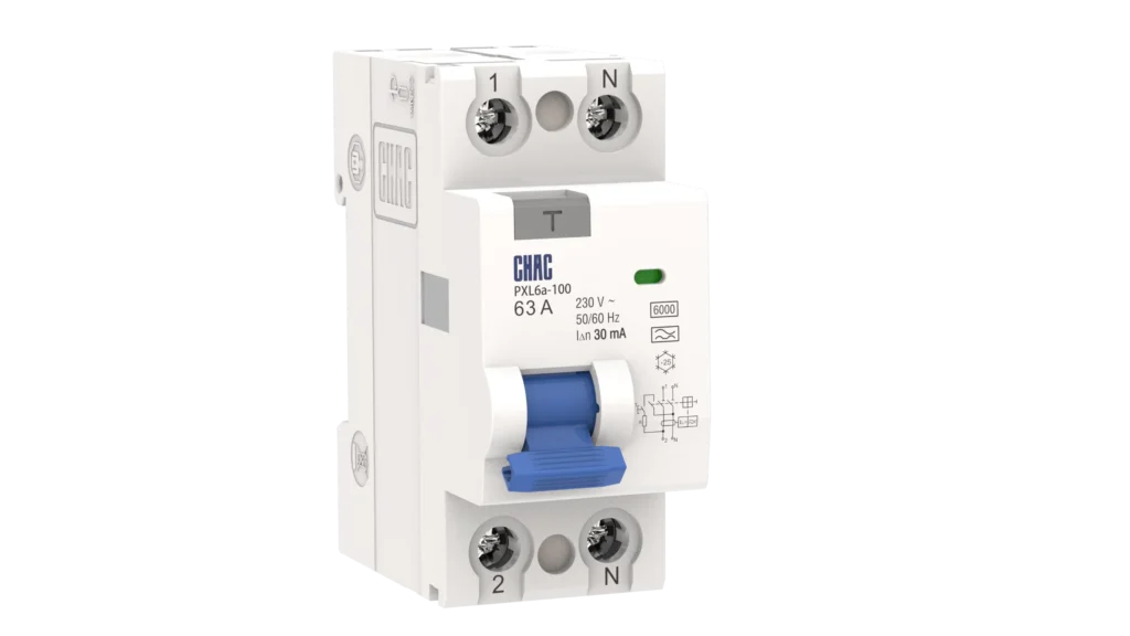
The existing PXL6a-100 product reference is retained below for model identification, not as a universal recommendation. Check the current documentation before specification.
PXL6a-100 Electromagnetic Residual Current Operated Circuit Breaker
Frequently Asked Questions
What is the difference between RCCB and RCD?
RCD is the broader term for a residual-current device. An RCCB is an RCD without integral overcurrent protection, while an RCBO combines residual-current and overcurrent protection. Use the exact device designation when specifying a board.
Can RCCB work without grounding?
An RCCB senses current imbalance rather than measuring an earth conductor directly. It can therefore operate in some fault conditions without a direct earth connection to the device. This does not remove the installation’s earthing and bonding requirements or establish complete protection.
Can I use type A RCBO for EV charger?
Only if the charger’s documented residual-current protection arrangement and applicable local rules permit it. Type A detects AC and pulsating DC residual current; it is not equivalent to smooth DC detection. Any claimed built-in DC detection or other protective function must be verified for the exact charger before a Type A RCBO is accepted.
What type of RCCB is needed for an EV charger?
The charger instructions, possible fault waveforms, and local installation requirements determine the type. Type B provides smooth DC residual-current detection, but that does not prove every charger needs an external Type B RCCB. Confirm which protective functions are built into the charger and which must be provided externally.
What size RCBO should I use for my EV charger?
There is no universal ampere rating for an EV charger. Confirm the manufacturer’s circuit requirements, configured maximum charging current, conductor capacity, installation conditions, and applicable rules. Then verify the RCBO’s overcurrent characteristic, breaking capacity, residual-current sensitivity, and waveform type separately.
How often should RCCB be tested?
Follow the device manufacturer’s stated test-button interval and the inspection or testing requirements applicable to the installation. Do not assume one schedule applies across all products and markets. Test-button operation does not replace the required installation verification.
References
- Schneider Electric, Electrical Installation Guide: Form factors of RCDs and Types of RCDs, both updated 5 August 2026. These explain device families and waveform selection, not certification of a CHAC model.
- European Commission: CE marking. This explains manufacturer and supply-chain responsibilities, not installation approval.
- UL Solutions: Panelboard Application Guide. This explains panelboard suitability, markings, and certification scope for the applications covered by the guide.
- Wallbox: EV charging standards, explaining May 2024 Swedish SEK Handbook 444 requirements and named Wallbox charger arrangements. This is a manufacturer example specific to its stated scope.
Linked source pages were reviewed on 7 October 2026. The comparisons concern protection functions and documentation requirements, not independently tested performance or pricing. This article is published by CHAC; no CHAC model-specific certification or EV/PV suitability is inferred from these sources.
What is the final check before choosing an RCCB?
The decisive distinction is between a correct current path and a correct protection specification. A borrowed neutral can defeat the intended balance even with a suitable device, while orderly wiring cannot make an unsuitable waveform type correct. Start with the circuit and equipment requirements, establish the earthing and neutral arrangements, then select the current-carrying rating, residual-current characteristics, and coordinated overcurrent protection. Before acceptance, verify the installation under the applicable procedure rather than relying on a successful test-button operation. These checks cannot be replaced by a familiar product name or conformity logo. For a model-level discussion, review CHAC’s residual current circuit breaker information and request the wiring and coordination documents needed for the intended project.