Voltage Unbalance Calculator
Calculate three-phase voltage imbalance from three line-to-line RMS readings using the maximum deviation from average voltage. Includes the formula and an example.
Check three-phase supply voltage before reviewing motor or equipment operating conditions.
Result
Voltage unbalance
1.25%Preliminary calculationUnbalance % = max |Vline − Vavg| / Vavg × 100Magnitude-deviation method. Does not calculate negative-sequence voltage, phase angles, motor derating or a protection setting.
Why this result?
Formula and method
Calculate three-phase voltage imbalance from three line-to-line RMS readings using the maximum deviation from average voltage. Includes the formula and an example.
How to use this calculator
- Measure the three line-to-line RMS voltages under comparable conditions.
- Enter A–B, B–C and C–A readings.
- Compare the result with equipment-specific limits.
Calculation limits
This method uses only voltage magnitudes. It cannot diagnose phase sequence, phase-angle errors, transient conditions or negative-sequence components.
Voltage imbalance formula: maximum deviation from average
This method compares three line-to-line RMS voltage magnitudes with their arithmetic average. The largest absolute deviation is divided by that average and expressed as a percentage. A correct average voltage does not mean all three phases are equally supplied.
Input notes
| Input | What to check |
|---|---|
| Three readings | Enter A–B, B–C and C–A voltages. Do not mix line-to-line and phase-to-neutral readings. |
| Measurement conditions | Use readings taken under comparable loading and supply conditions. Changing loads can make sequential readings misleading. |
| Equipment limit | Compare with the motor or equipment manufacturer’s requirements. The calculator does not apply a universal pass/fail limit. |
Worked example · initial form values
400 V, 395 V and 405 V line readings
A–B = 400 V · B–C = 395 V · C–A = 405 V
Average = (400 + 395 + 405) / 3 = 400 V
Maximum deviation = 5 V
Voltage unbalance = 5 / 400 × 100 = 1.25%
1.25%
Although the average is 400 V, the line voltages are not balanced. Review the result against the equipment limits and investigate the supply before drawing a conclusion about operation.
Why unbalance matters to motors
- Voltage unbalance can produce disproportionately large current unbalance and extra motor heating. Motor derating guidance is equipment- and method-dependent; a calculated percentage is not an overload setting.
- This magnitude method does not determine phase sequence or negative-sequence voltage. Those assessments need phase-angle information and suitable power-quality measurements.
Frequently asked questions
Does this determine negative-sequence voltage?
No. It uses the largest magnitude deviation from the average of three readings. It does not include phase-angle measurements or calculate sequence components.
Can I use highest minus lowest voltage over the average?
That is a different calculation. This tool uses the greatest individual deviation from the average, not the difference between the highest and lowest readings.
Does 1.25% mean the motor is safe to run?
The number alone cannot establish that. Check the manufacturer’s supply limits, loading and derating requirements, and investigate the cause of unbalance.
Is this the same as the IEC voltage unbalance factor?
No. A negative-sequence to positive-sequence voltage ratio requires sequence-component information. This calculator uses only three voltage magnitudes and reports maximum deviation from their average.
Need help choosing a CHAC product?
Send the system voltage, load current, and installation conditions with your inquiry.
Application example · Illustrative inputs
Checking three line voltages before reviewing a motor circuit
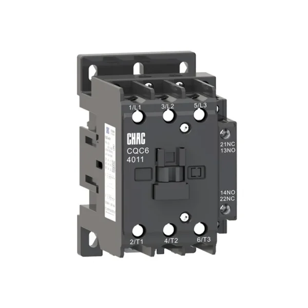
Before investigating a motor circuit, compare all three line-to-line RMS voltages under the same operating conditions. Using 400 V, 392 V and 408 V gives an average of 400 V and a maximum deviation of 8 V, or 2.00% by this method. The figure helps frame a supply investigation alongside CHAC CQV2, CQR2 and CQC6 product data. It does not identify the fault or establish an acceptable motor limit. A thermal overload relay must not be described as providing dedicated voltage-unbalance protection unless its exact documentation confirms that function.
Product data: CQV2 Series Motor Protection Circuit Breaker · CQR2 Series Thermal overload relay
Related CHAC products
Review motor-circuit equipment alongside the voltage measurements. Confirm any imbalance-protection function separately.